
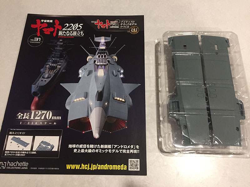
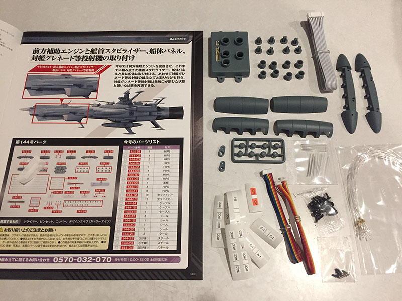
Volume 31 looks like an easy ride. A couple hull panels for the top of the ship. But wait a minute…

PSYCH. There’s another distributor box hiding underneath them! Here we go again…
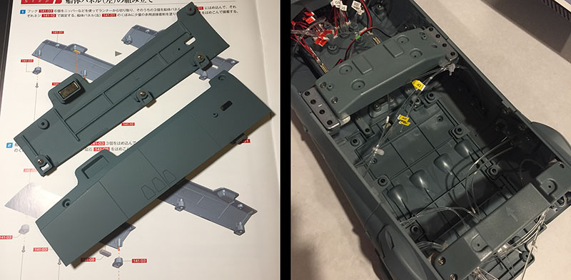
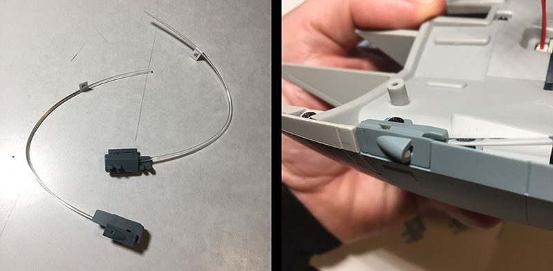
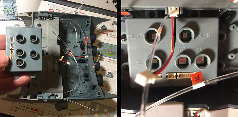
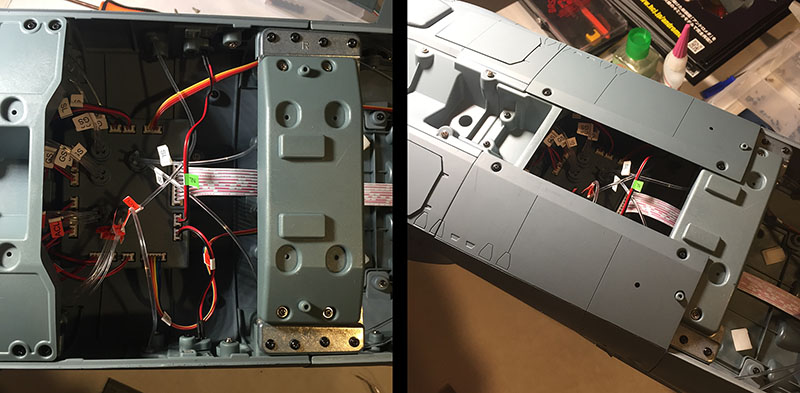
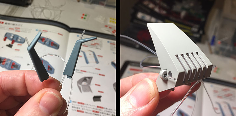
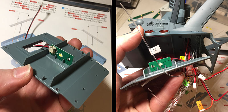
The panels are no big deal. Put three clips on and install a magnet. Done. At right is the compartment the box will go into, situated at the rear of the segment we’ve been building.
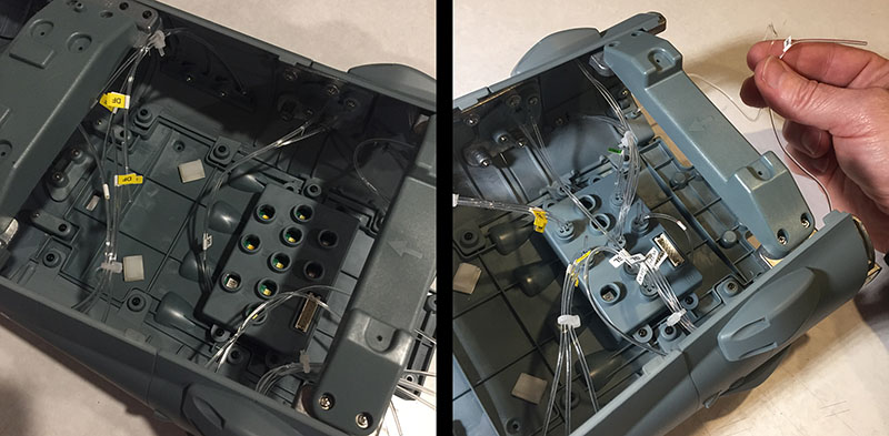
At left, the box is in place. No need to review the fiber-plugging procedure. They all found their ports without a fuss. Two fibers left, probably waiting for companions and a future plug. That’s all for this volume. I’m noticing that the plugs and caps aren’t as tight-fitting as they were on the Yamato model. It makes me a little uneasy. Remember that for later.
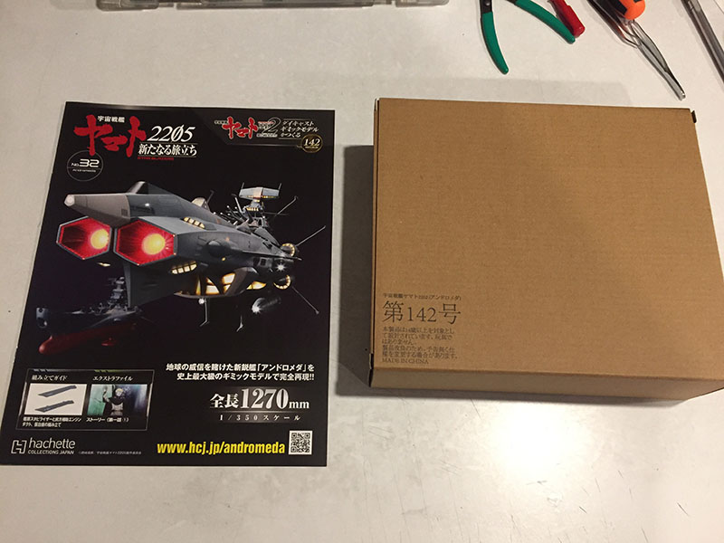
Volume 32 is packaged differently, as you can see.
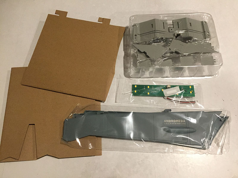
Inside the box was the tray of parts and some more cardboard.

We’re moving down into the underbelly of the ship’s forward section. Those two large pieces will form the “keel.” The other parts belong to the big “intake.”
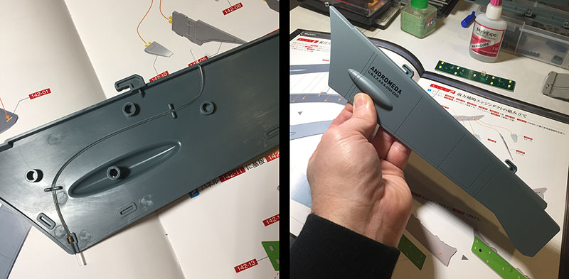
The keel goes together like the wings did; two halves with a single fiber optic thread inside. They have to be glued, which rankles me a little bit. When I got into this, I kinda thought we were past the need for glue. But nope. And I went with the super glue on this. We’re playing for keeps.

All of these parts will form the leading end of the intake. They’re meant to be glued onto the translucent piece.

The directions say to glue them in, but they snap in just fine and don’t need any reinforcement. Next step (at right) is to put these two pieces together. They will sit right behind the translucent part. All the yellow squares are LEDs.
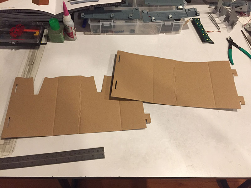
That leaves the cardboard parts. Deeeeep breath. This is gonna be a tough one. Okay, here we go…
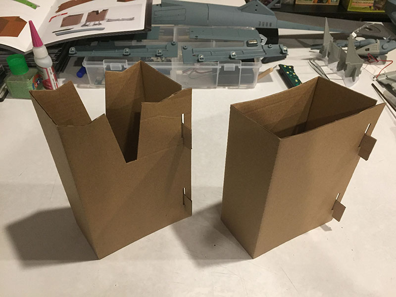
There. Whew. I need to go lie down for a bit…

Here’s volume 33. We’ve got a whopper of a piece this time.
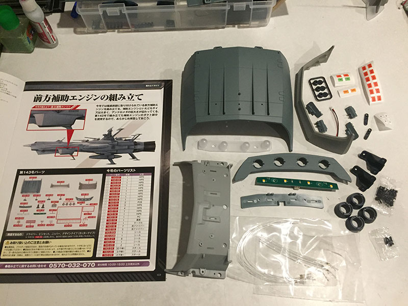
This is the entire structure for the intake underneath the forward section.

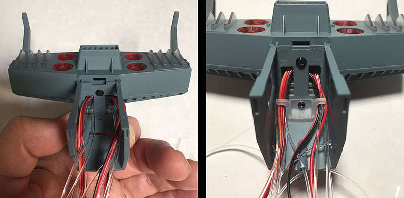
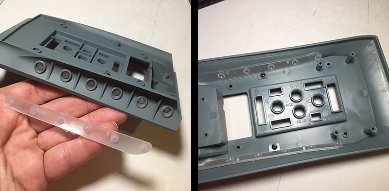
We’re off to a smooth start. Just putting two pieces together. But then flip it over. Look at alllllll those receiver points. This is going to be a busy place.
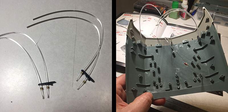
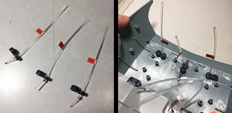
Next, string some fibers together and put them in place. They’ll lead to two lights on each side and one in the center.
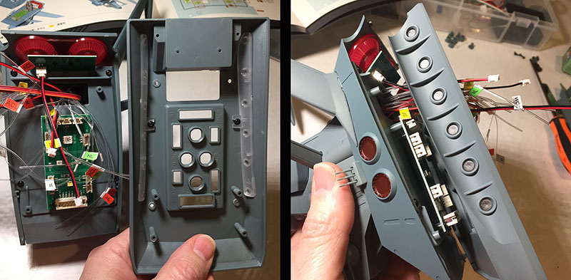
Now a big sort of clamp goes over them. They try to escape, but they lose the battle. Trim the end bits, and we move on.

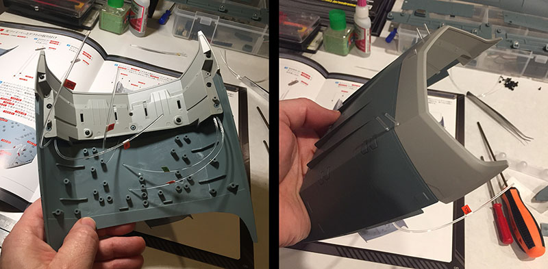
Next, the translucent part with all the fins gets installed, and the panel holding all those LEDs slides in right behind it.
Now a “roof” goes over all that, and the front end of the intake is finished. It’s amusing to think about how a few decisions by Mecha Designer Kazutaka Miyatake back in 1978 led to all this engineering and craftsmanship.
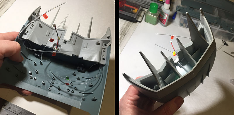
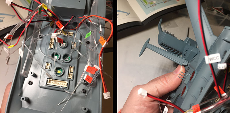
Next, we thread up some more fibers and install running lights on either side of the intake.
Thread up three more, and they go in the rear portion. These lights will point down.
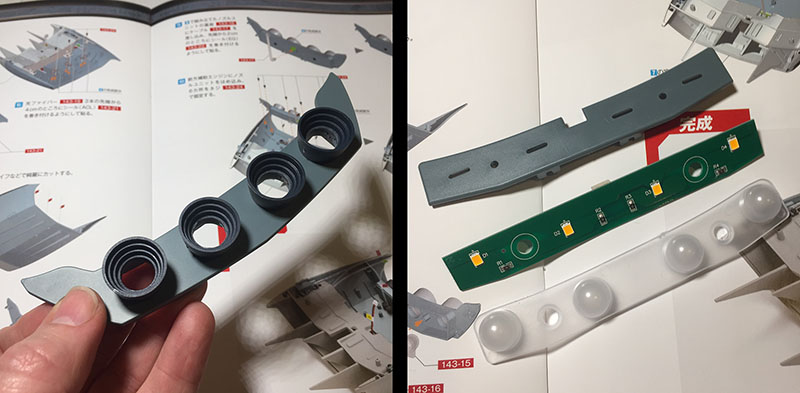
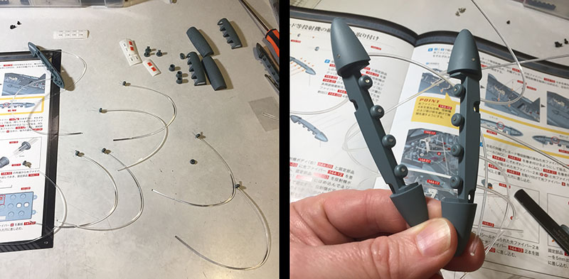
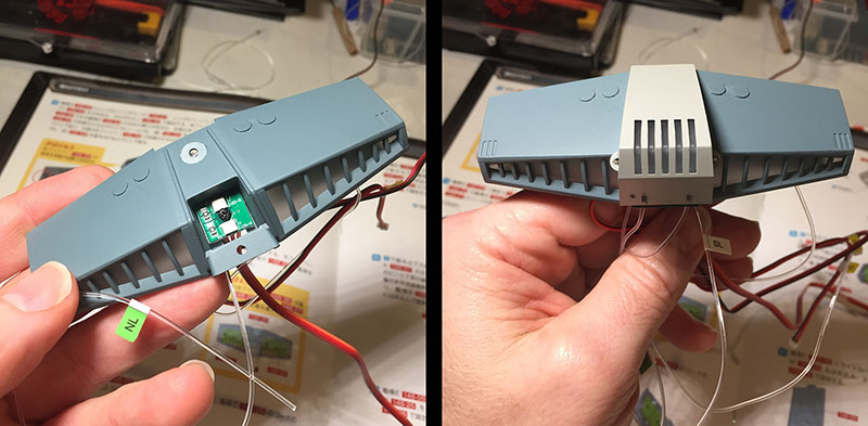
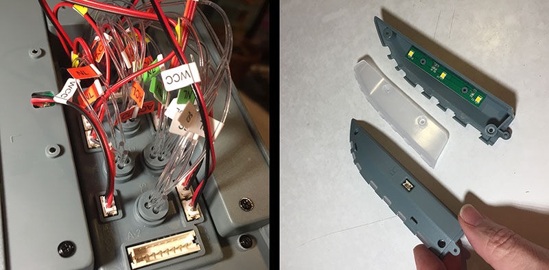
Here’s the rear panel with its four booster engines. First the cones get glued into place, then we assemble a panel to fit right behind them. The circuit board houses four LEDs, one for each cone.

Now it’s all in one piece, and attached to the backside.
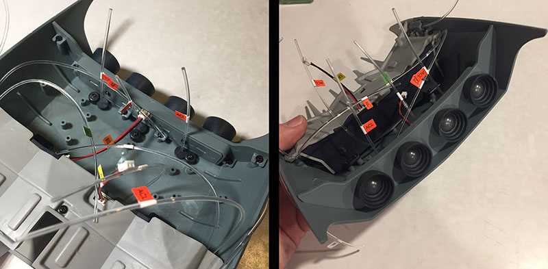
This portion slides into position, and now the back end of the intake is done. That’s it for this volume, but there are still a lot of receiver points to be filled.

Volume 34. I won’t sugar coat it. This one was a MOFO.
Look at all those parts. LOTS of wiring. LOTS of major assembly moments. And things went wrong. I wish I could send this report back to myself as a cautionary tale.
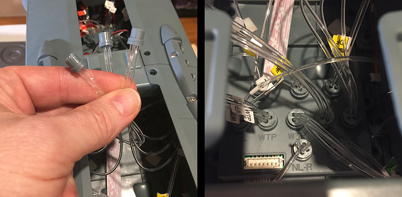
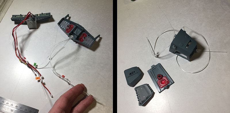
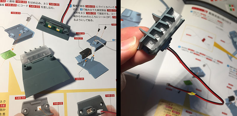
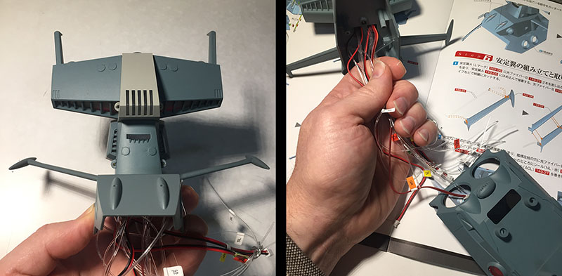
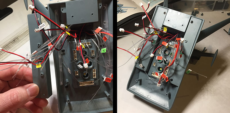
Step one, install this distributor box into the intake. Not much room left, but it fits.
Step two, cap and plug in all the fibers. The long ribbon wire will snake up into the main hull and feed power to this box.

Step three, slide the keel into place. Easy move; insert and slide forward. The thing is, though, this big heavy hunk of hull has been sitting flat on my table the whole time. Now it can’t any more.

Step four, snake the ribbon wire into the hull cavity and attach the entire intake piece. Screws go into it from the interior.
And now you see what those cardboard pieces were for. This is how it will rest for a while as we continue forward. Eventually, it will have a much bigger and more solid stand under it.
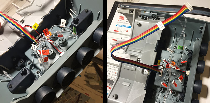
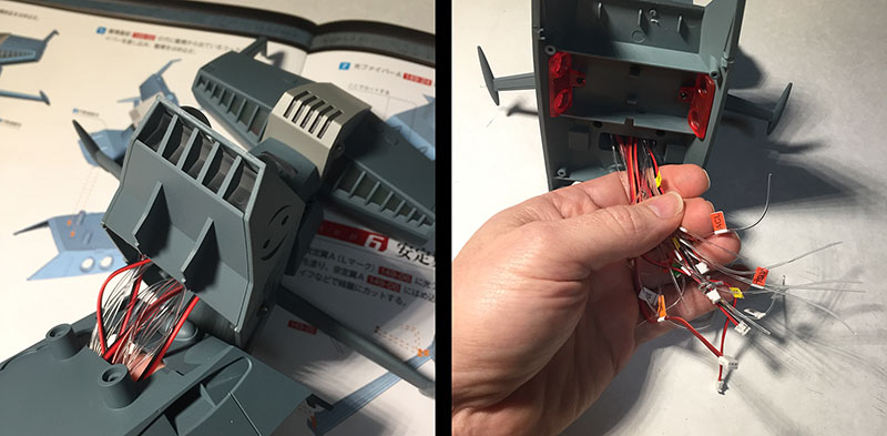
At left you see the intake’s ribbon wire coming in from the top. Below that is a second, much bigger ribbon wire (white and pink) that will deliver power to this box from a source to be assembled in the future.
At right, those upper hull panels that have been sitting around for a while finally get installed. We’re beginning to box up the forward section.
And there we go. Four upper panels in place. That means we’re done with this part, right?
Oh, no no no no NO. Now all the fiddlybits have to go into the two side bulges. (They actually call them “bulges” in the instructions. No special name for these.”
They fight me a little. Getting all those fibers to conform is always tricky. But I keep at it and they secure into place. But now there’s a new mess of fibers sticking down into the cavity, and a lot less room to manuever.
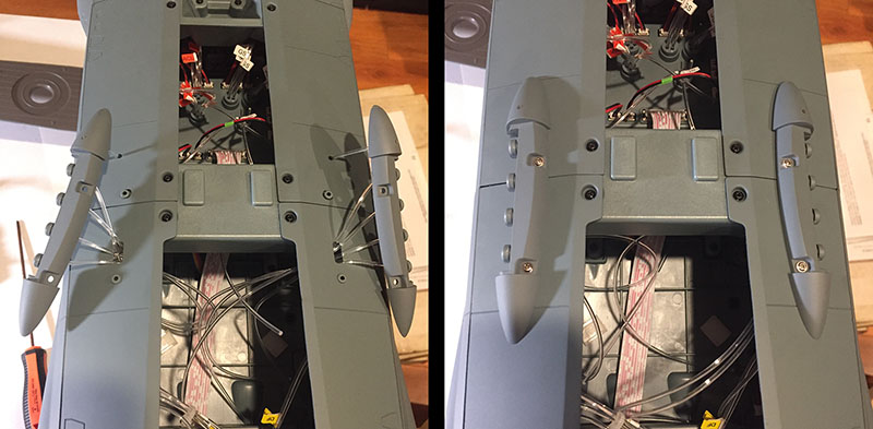
And here’s where the trouble happened. At left, you see all the fibers capped and trimmed. The trimming was the fatal flaw. Despite following instructions, one fiber – just one – was cut too short. When I plugged the cap into the distributor box, it popped right out. That single fiber was too short to go where it was supposed to.
Remember what I said earlier about the caps being looser than they used to be? This is where it became a serious problem. There was nothing holding this fiber in. But leaving it unplugged would have resulted in a single light being permanently unlit, in a ROW of lights. It would stick out like a sore thumb.
The only option open to me was to fit it into a neighboring plug, swapping it out for one of those dummy fibers that was just taking up space. And because these plus are so loose, dismantling one led to a nightmare of fiber spillage. And also, after those upper hull panels went on, it severely reduced the space I had to work in. Yamato had practically none, due to the various motors that drive the moving parts. But this was still the worst case scenario.
I actually had to peel off layers of clothing during this process as my temperature rose, but…after MANY failed attempts, I finally got that short fiber into a slot and it held. It will probably shine a different color than its neighbors. But I prefer that to no light at all.
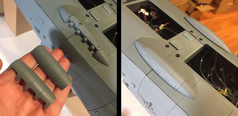
With all that behind me, the last step was a simple one; cover up the bulge with one of these two option parts. One exposes the lights, the other covers them up. I’ll decide which one to put on when I see the results of my fiber-hacking.
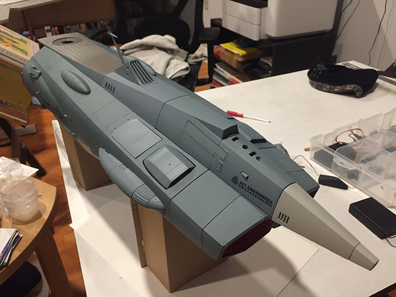
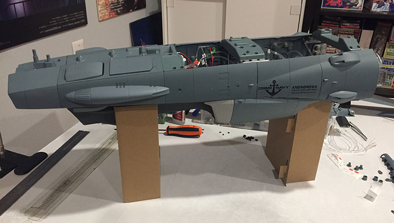
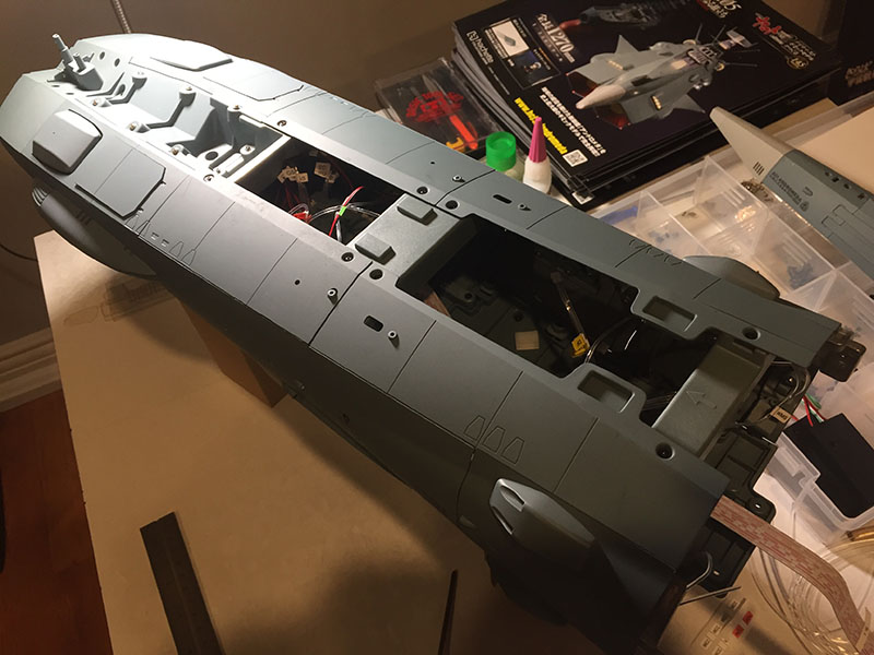
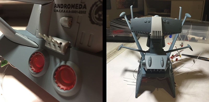
And there we go. The front section of the ship is finished. The upper section isn’t bolted down yet, but I can’t just leave it sitting off to the side any more.
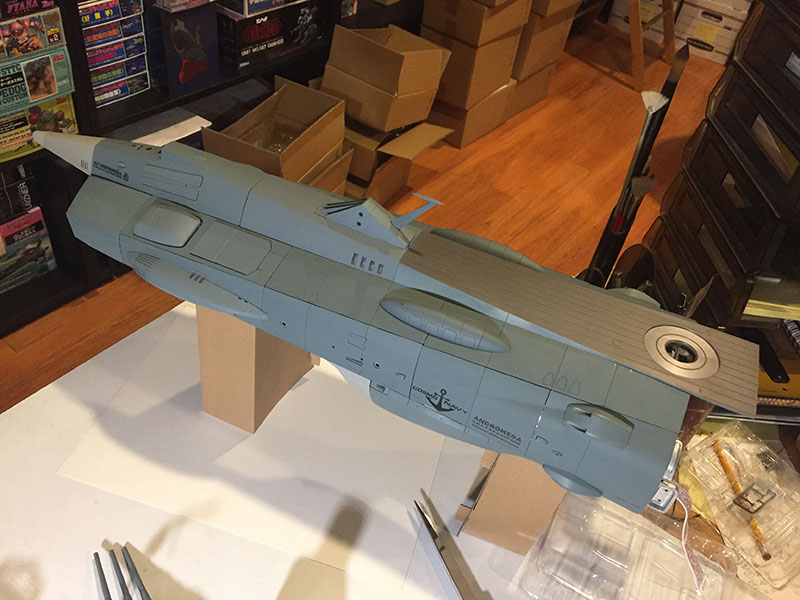
The current length is 25″ from end to end. That’s about half. It’s already a monster, in more ways than one.

Volume 35 looks rather familiar…
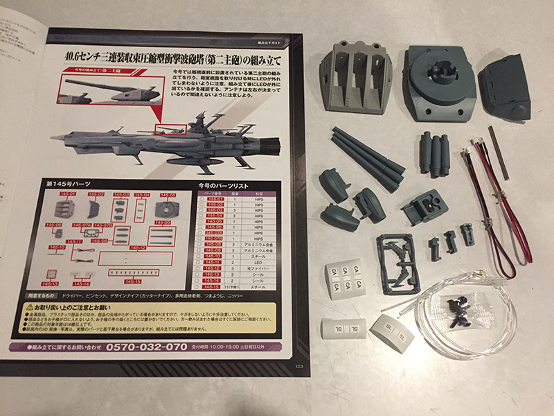
It’s the second main gun turret. The first one was split between Volumes 10 and 11, but this one came in a single package. That makes me wonder how Hachette decides to divide up their volumes. You’ve seen how they get more and more packed as time goes on. And there are some whoppers still to come. it seems a bit haphazard, but it all comes out in the wash.
The assembly here was the same as 10 & 11, so no need to repeat. However, speaking of repeats…

Here’s Volume 36…
…main gun turret #3.

And here’s Volume 37…
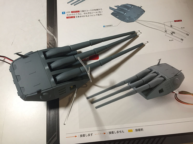
…main gun turret #4. All went together exactly the same way and have exactly the same problem.
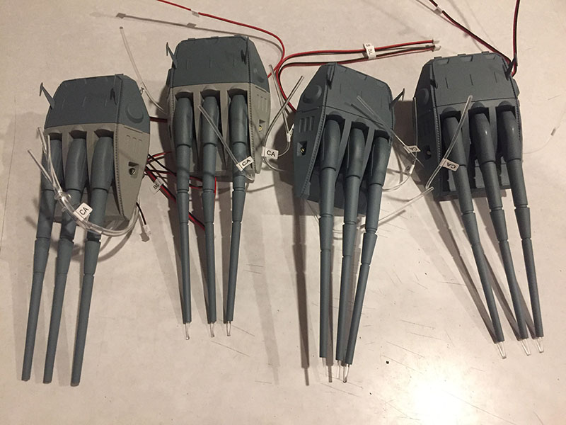
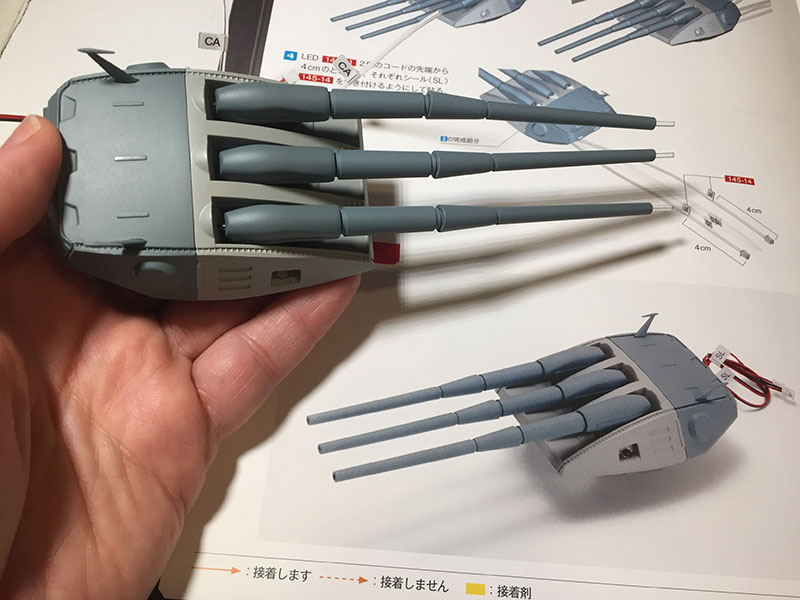
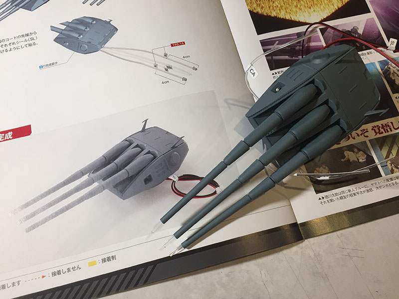
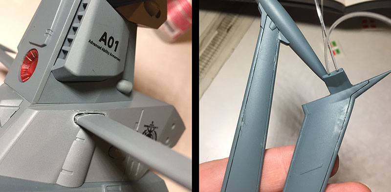
You can see it clearly here. None of the gun barrels are straight. That’s because they all contain fibers, and will be lit at their cannon tips. The curl in those fibers is so strong that the barrels can’t tame it. So what’s the solution?

Hachette must have known this would happen, because the instructions say to glue the barrels to their bases. Again with the damn glue. Really, after all the time and money and engineering, you still need ME to glue stuff together? Not cool. Especially not cool here. I chose not to do it with the first turret, but now it’s absolutely necessary. So here we go.
Regular cement has no grip at all, because the paint on these pieces actually repels it. So it’s super glue or nothing. After some thought, I decide the best method is to roll a cotton swab through a puddle and ream it into the barrel. The action of sliding it onto the base should keep all the glue inside.
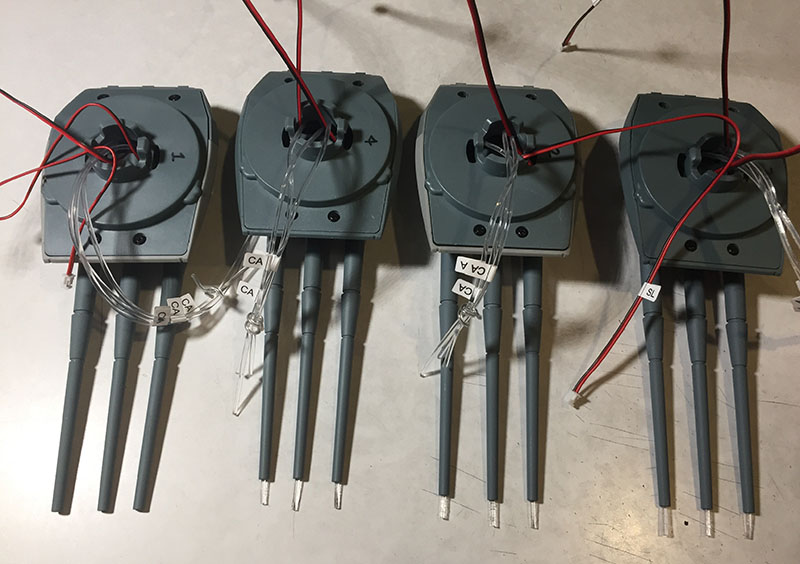
A few minutes later, they’re all glued together and they’re all holding with no overflow. The fiber tips can be trimmed later. Right now I’m just happy to have gotten through it without any mishaps. And I numbered each turret on the bottom, just so I can keep track of the order if need be.
Next, we’ll jump to a totally different part of the ship. I’m told it’s the most challenging part of the entire build. Hard to imagine it being harder than what I’ve recently been through, but we’ll soon find out.
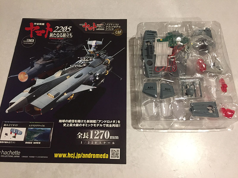
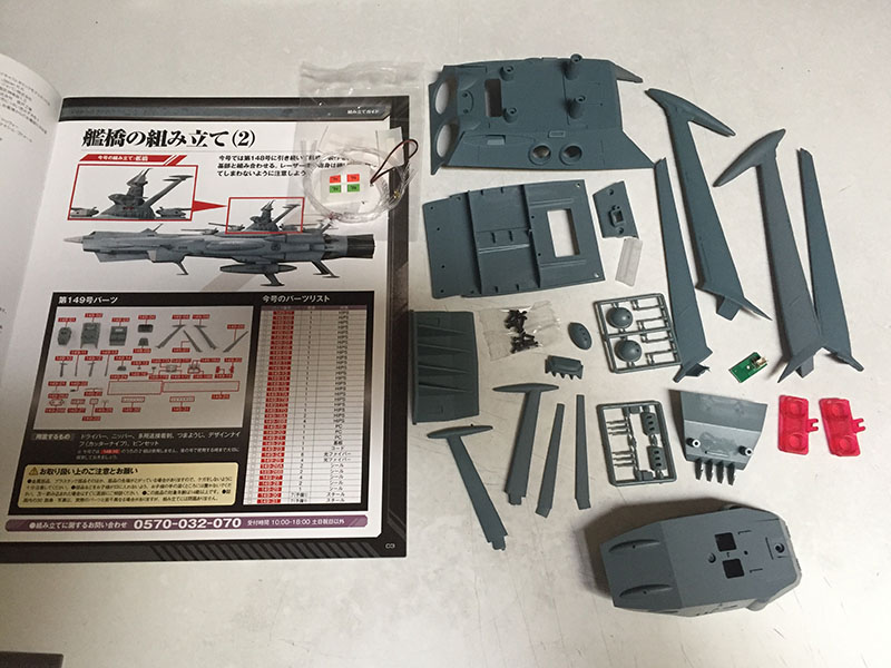
Hello, Volume 38. Here’s where the fun begins.

With this one, we’re starting from the top of the bridge tower and working our way down. Yamato‘s bridge tower was very, VERY difficult due to the incredible amount of lighting they asked us to stuff into a very tight space. There’s at least as much going on here.
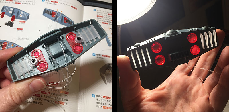
It starts simple with translucent parts in the backside of the bridge section.
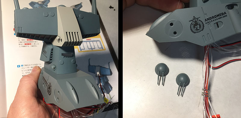
Then the two “horns” and the face of the bridge. This is already shifting gears from the previous volumes. We’re focusing on very small parts, too small to be screwed together. That means they can only be glued together. Those little half-dome running lights on the bridge face were the first tough ones, because they each had to contain a fiber. Fibers HATE being contained.

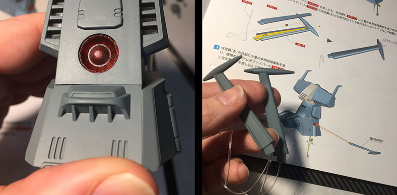
The front side of the bridge structure is next. Two fibers go in first, then get covered up by circuit boards with LEDs on them. I’m leaving out the part where it took four tries to get them configured correctly. Again, fibers HATE being contained. They will pop and leap and jump the second you take your fingers off of them.
A smaller LED board goes on the front, then gets covered by the “face.”
Left: the front and back are now fully wired up. The only way to keep that spaghetti under control is to twist-tie it. The wires and fibers will travel all the way down to the bottom of the tower and get handled a lot on the way there.
Right: a few sub-assemblies for the next step.

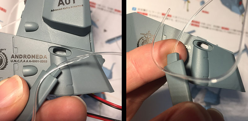
Next, we’ll attach the “neck” to the “head.” In order to do that, the noodles have to thread neatly through those two rectangular slots at the top of the neck.
Right: there’s no way for this process to be rushed. You simply have to follow the instructions and pull them through one at a time to avoid a noodle jam. Next, see that translucent part? It has to pin all the noodles into place. It seems impossible.
But after careful pushing and prodding, it comes together. This is kind of a preview for what’s to come as the tower grows toward its base. We’ll get there in two more volumes.

Here’s the head and neck all put together. As you can see at left, the translucent part that pins the noodles down actually protrudes a little out of the front. The way they designed these parts to multi-task is quite impressive. But there are some things coming up that do NOT impress me even a little bit. Settle in for some griping.

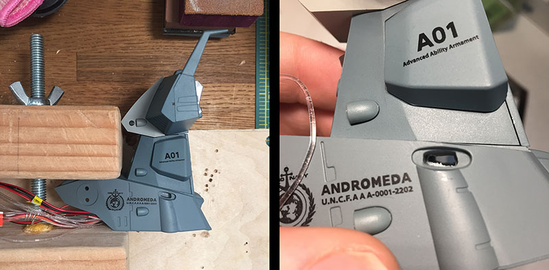
Volume 39 earned itself a very sketchy reputation, and not just for how packed it is.
These parts will form the middle third of the tower. One part in particular became quite notorious.

When this volume was originally issued, there was a TYPO on the insignia. You can see it in the top version: “0005-2202.” That is not the ship number for Andromeda. Instead, it’s for Antares. When this was discovered, Hachette immediately announced that the part was going back into production to correct the error, and would be issued in a future volume. It took about a month to arrive.
Those who didn’t notice the typo and started building would have been put in an impossible situation. By the time the corrected version showed up, so many pieces would have been glued together you could not disassemble them to fix the model. They’d be stuck with the typo. Everyone who chose to wait were frozen in place, since that part was the first one to be handled in this volume.
None of this affected my build, because I chose to wait until all 60 volumes were in-hand so I could review online blogs and take notes. It was just a really dumb mistake by Hachette. To this day, I can’t imagine how it was made.

We begin volume 39 – so far my LEAST FAVORITE OF ALL VOLUMES – by completing the head and neck, attaching an LED board to the support, and threading all the noodles into it. This is the second time they all get threaded. I started out by not noticing the support was backward, so I had to pull them back out and thread them all again.
Left: everything’s threaded and the neck is connected to the support.
Right: the instructions said to put these little gun turrets on next, but one of the blogs said to wait until the end, since they’ll interfere with some of the work to be done. The last thing I want is to stress over snapping those tiny gun barrels off, so I follow this advice.
Left: a little “ledge part” gets attached to the back. I mean glued. It gets glued.
Right: now the two side-fins get glued together with a fiber inside. See the yellow on the diagram? That indicates glue. There’s SO MUCH GLUING in this volume. I hate every second of it. Getting a fiber to sit still as you attempt to glue pieces around it is an impossible task. So the fiber itself has to be glued in place.
With that finished, I get my first rude surprise. The fiber is supposed to go through that slot, followed by the base of the fin. But the slot is closed up. Remember, this is the replacement support for the one with the typo on it. So I go get the “typo” version and…look at that. An open slot.
This tells me the replacement part was rushed out so quickly they didn’t have time for proper quality checks. I’ll have to bust through the slot myself.
Fortunately, I live with a woodworker (she carves puppets) and she’s got a drill set that can handle this. In no time flat, she re-opens both slots for me. Whew.
Next, a front panel comes together with a translucent part and LEDs to light it. This piece screws together. I’ll take screwing over gluing any time. Maybe I should rephrase that…

Two more quick sub-assemblies: Translucent red panels get screwed into the next support part and a little gun battery gets glued onto the back. Okay, simple enough. But the next rude surprised is coming right up.
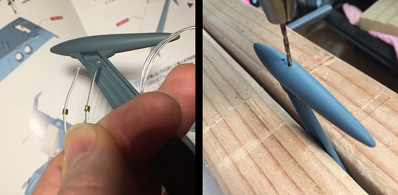
The next step is to thread two fibers into one of the big side wings. The problem is that the fibers are thicker than the holes Hachette made for them. So, it’s back to the wood shop for some precision drilling. This has to be done for both wing tips. What a dumb oversight this was.
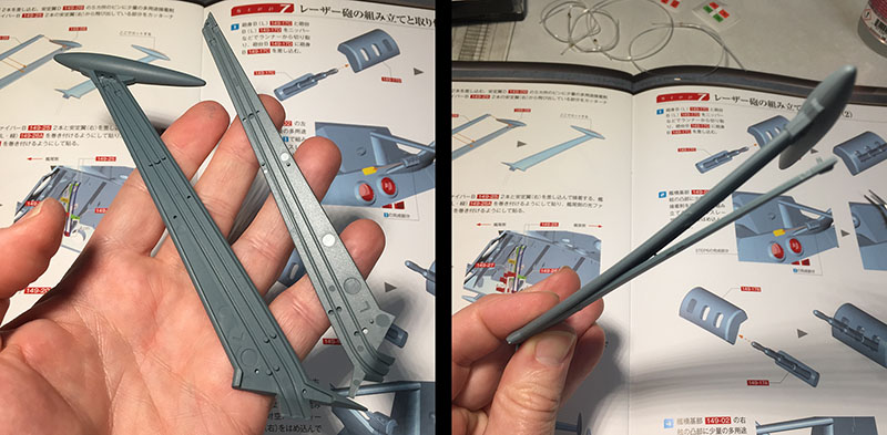
Now we’ve reached the WORST part of the WORST volume so far. The wings each have to magically contain TWO fibers and be glued together. At right you can see the major problem: one of the sides is curved and the other is flat. This isn’t a mistake, both sides curve equally. But the flat side will have to conform to the curved one. That means regular glue won’t cut it. Only super glue is going to hold this thing together. And I HAAAAAATE having to rely on superglue.

Left: like before, you have no choice but to glue down those fibers into their channels. This has to be done inch by inch. Flood part of the channel with glue, press the fibers in until they stay put, then move down an inch and repeat. Eventually, they behave. Fortunately, regular glue is up to the task.
Right: but now we have to bring in the super glue. The reason I hate it is because it’s nearly impossible to keep it where you want it. As soon as you press parts together, it’s going to seep out through some crack somewhere. This is where I point the finger of blame directly at Hachette. So much of this model is engineered so brilliantly, this seems like they just got lazy. Bandai models don’t require glue at all any more. You’re telling me you couldn’t think of any other way for this part to go together???

Left: there we go, an accident already happened. One of the wingtips got dragged through a tiny bead of superglue, and now the surface is ruined forever.
Right: all the pieces are stuck together, clamped, and drying. When I open them up later, I’ll find that the glue worked, but seeped out all over the place. First order of business was to scrape off all the tissue that got stuck to the glue.
While the big wings are drying, I glue the smaller ones on. With super glue, of course. Regular glue won’t support them.
The next step is to attach the next support piece, so all those noodles have to get threaded (again) into that rectangle at lower right.
They go in one by one and come out the other side. I should mention that every time this threading takes place, more noodles get added from the section that just got sealed up.
Before we move on, I have to gripe one more time about being forced to use superglue. Here’s the inescable result: glue burns. When the stuff dries, it doesn’t go clear. It looks terrible, and to me it will glare at me every time I look at the finished model. Could I improve my glue game and avoid these accidents? Sure. My gripe is that with a model this carefully engineered – and EXPENSIVE – I shouldn’t even have to bring my glue game to the table.
Anyway, the little turrets go on (regular glue), the big wings go on (frickin’ super glue) and we’ve reached the end of this rotten volume. I want my money back for this one.

Volume 40 is another one with a LOT of parts inside. With this, we’ll reach the bottom of the tower.

I should mention that most of Volume 38, and all of 39 and 40 were built on a Saturday, and it took about twelve hours from start to finish. I accomplished very little else, but I had to take an hour off to go running between 39 and 40, or I might have just thrown the whole thing out a window.
First step is to slide an LED board into this plate and attach it to what’s been completed so far. This will become the “floor” of the support structure we just finished. So, of course, there’s another opening to pull all the noodles through.

Left: they’ve all been pulled through (with more added since last time) and the “floor” is screwed on. The tower is becoming harder to handle as it gets bigger. Not because it’s heavy (it’s all plastic), but because there are fewer safe places to grip it for leverage. You run the risk of popping off a wing or putting pressure on something that can’t take it. Working on Yamato‘s superstructure was exactly the same. I found only ONE way to safely hold the thing and sweated through it the entire time.
Right: a big circuit/LED board gets bolted onto the “floor.” This is where all the noodles will finally go to rest.

A couple of small sub-assemblies to clear the head. No glue required.
Now, finally, we’ve reached the bottom-most support structure for the tower. A couple translucent parts get screwed into the sides. When I flip it over, I see a familiar arrangement of ports and call letters. The end is in sight.

But first, one last stab from the pit of hell. This red translucent part gets attached to the inside of that back panel. It’s totally big enough to screw in, but there’s no attachment point of any kind. Just a flat surface. I have to glue this onto a flat surface. And of course it can only be done with superglue. So I take a deep breath and try my best…and YEP. There it is, seeping out from the middle to put another bloody glue-burn on both of these red ports. Screw you, Hachette. I mean that literally.
All right, here goes. The base of the tower structure is ready to install. This is the last time I’ll have to pull all the noodles through a hole. There’s now a total of 26. It takes a few tries to get everything properly configured, and then the base gets successfully screwed on.
Left: there it is. Up until now, all the distributor boxes have been installed as self-contained parts. This one sort of formed itself, which was pretty clever.
Right: remember what I said about having very limited ways to safely hold onto the structure for leverage? Still true. I popped a wing off while bolting the base on. This will be the second time I’ve superglued it in, so I’ll have yet another rotten glue-burn glaring at me for all time.
Now the last of the sub-assemblies goes on. These segments contain LED boards to light those round side-ports. When they’re in place, they add two more noodles to the riot. With all that done, the time has come to tame all those blasted noodles.

The first phase (left) is to isolate all the wires and plug them into their ports. They go in without a fuss. The second phase (right) is to gather up all the fibers by their individual labels and go through the capping process I’ve already described elsewhere. These caps feel nice and tight. No danger of slippage. The only tricky part to all of this is untangling everything one strand at a time to keep them from interfering with each other.
By the end, I’ve taken all the fight out of these noodles and brought them home. This point was the absolute worst part of the Yamato model. Not just for me, but for EVERYONE. The problem there was too much spaghetti in too little space. You had to keep un-capping and trimming down the fibers until their mass was reduced enough to fit inside the tower. We seem to have dodged that battle here, but it’s not over yet.
At right: two more sub-assemblies and we can call this volume done.

This photo represents one long-ass Saturday.
yeah, while I am jealous of those who have one of these there’s no way I could have survived putting one of these together…