
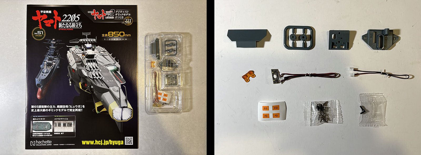
Here we go with Volume 51. It contains the flipside parts of Vol. 47, which was the smaller of the two popup signal lights.
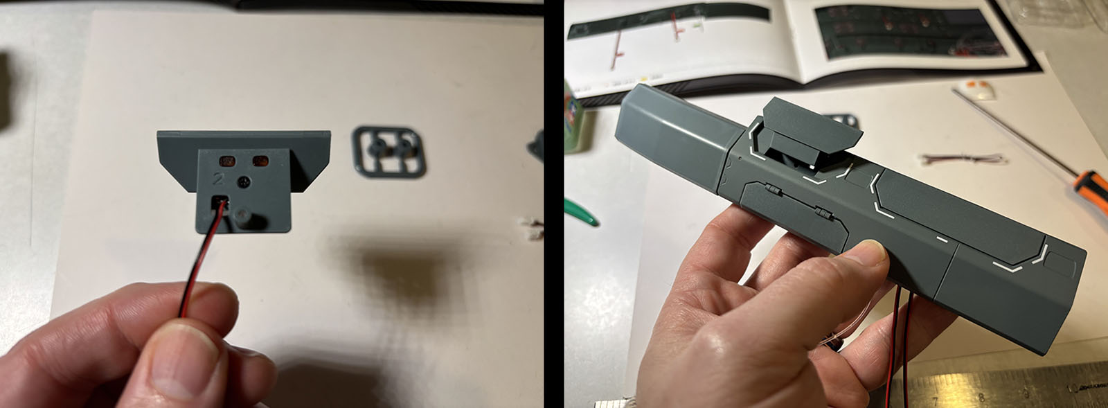
Various pieces come together, it slots into the hull segment and gets secured into place. It slides up and down easily.
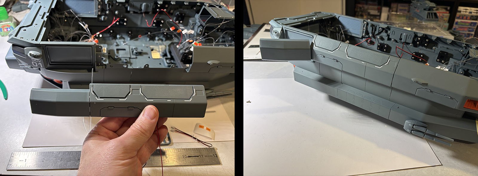
The hull segment is now finished and gets bolted onto the starboard side to fill the last remaining gap. It’s another situation where the confined space doesn’t allow me to use the large screwdriver, so it’s a struggle to get all seven of the screws in. But one by one, I prevail. It would be easier if I could lay the ship on its side and bore straight down on those screws, but the little gun turret at the bottom right doesn’t allow that to happen. So screw you, little gun turret.
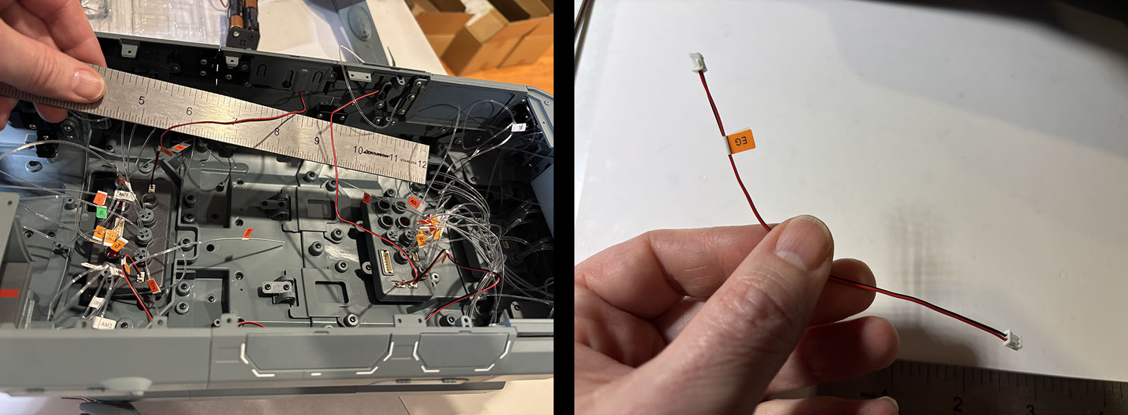
With that milestone out of the way, there’s some simple wiring to be taken care of. Each of the popup signal lights has its own wire that connects to a distributor box. Then (at right) there’s one more wire with plugs at both ends.
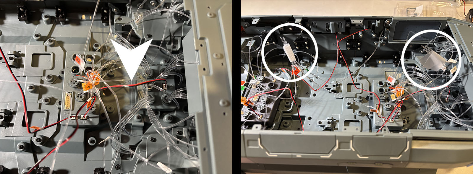
This one is a relay wire that connects two distributor boxes together. Specifically, the two near the stern. It will relay power from the larger one (center) to the smaller one (right). No problem with installation.
From here we’ll be putting aside the main body of the ship for a while, so I decide to gather up the fibers that haven’t been plugged into anything yet. There’s still kind of a lot. The fact that they’re not being capped at this point tells me there are still more on the way to be combined with them. After all, there’s an entire hangar deck to be installed here.

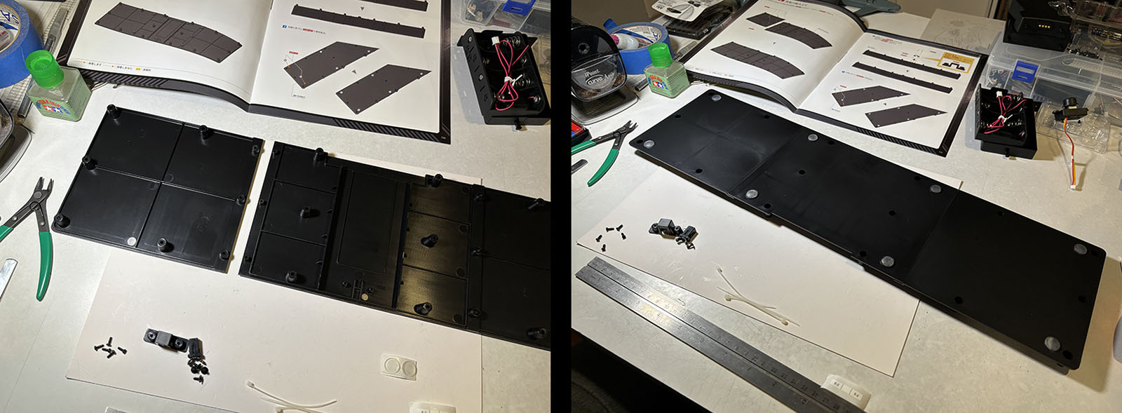
Vol. 52 is the first of many devoted to the display stand. Eight of the ten volumes in this set are just for the stand. Anyone who built this model one volume at a time as they came out weekly had to spend TWO MONTHS on it. Waiting until I had them all lets me whiz through all of them in under an hour.
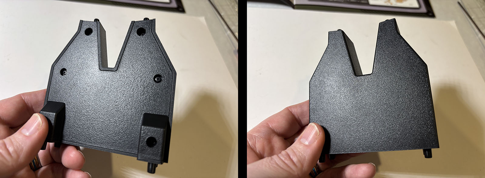
The first volume just gives us one of the pillars. Screw the two sides together and it’s done.
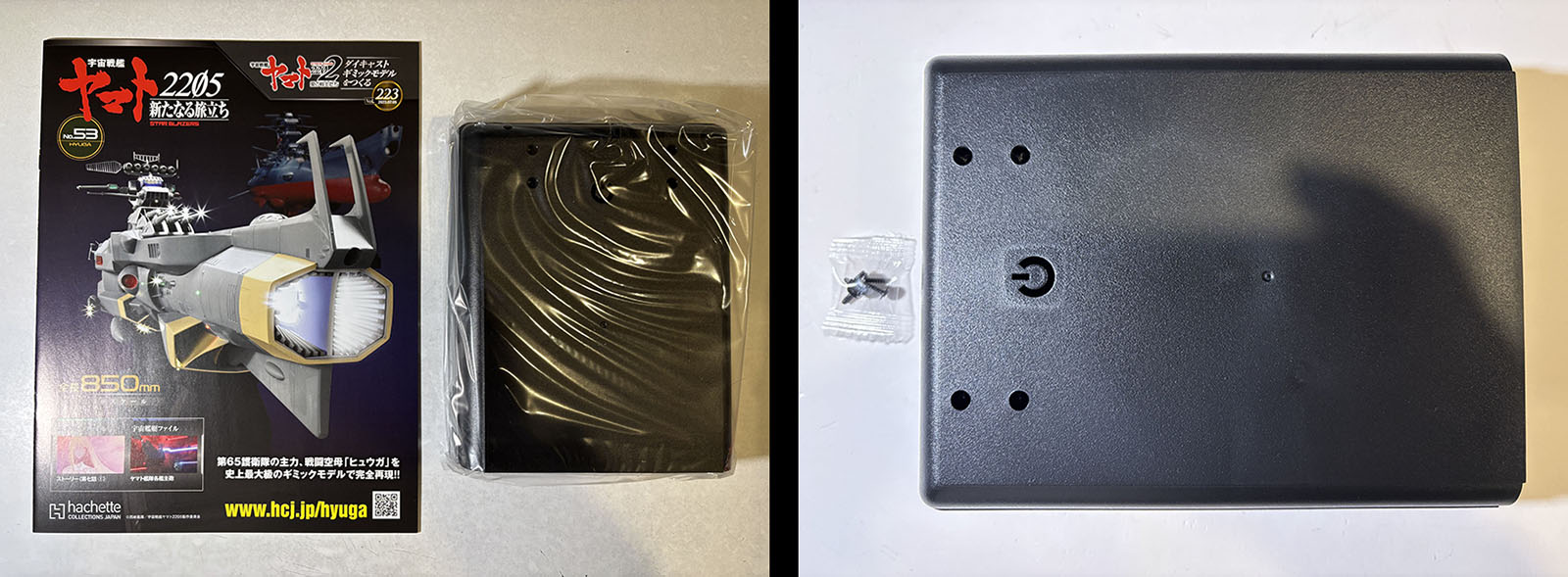
Vol. 53 gives us the first of three base segments. The whole stand is assembled like a clamshell with electronics inside. What I’m calling the “base” forms the top of the shell.
The only operation this time is to attach the pillar to the base. But I ain’t playin’ that game. Why? Because I’ve been down this road before. Attaching it now would make the next few steps a lot harder than they need to be.
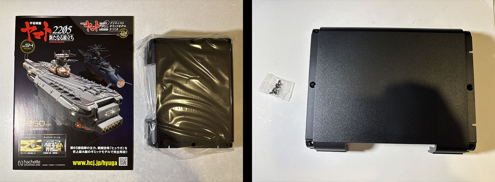
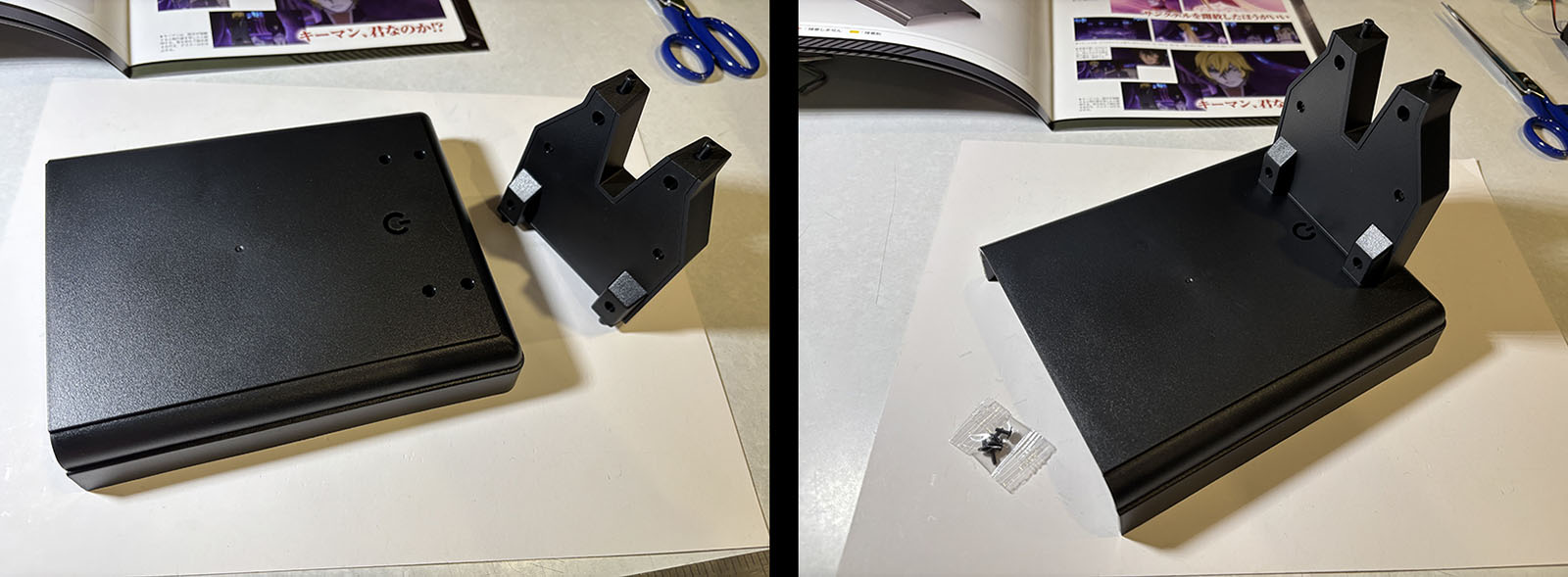
Vol. 54 contains the second base segment. This one will go in the middle.
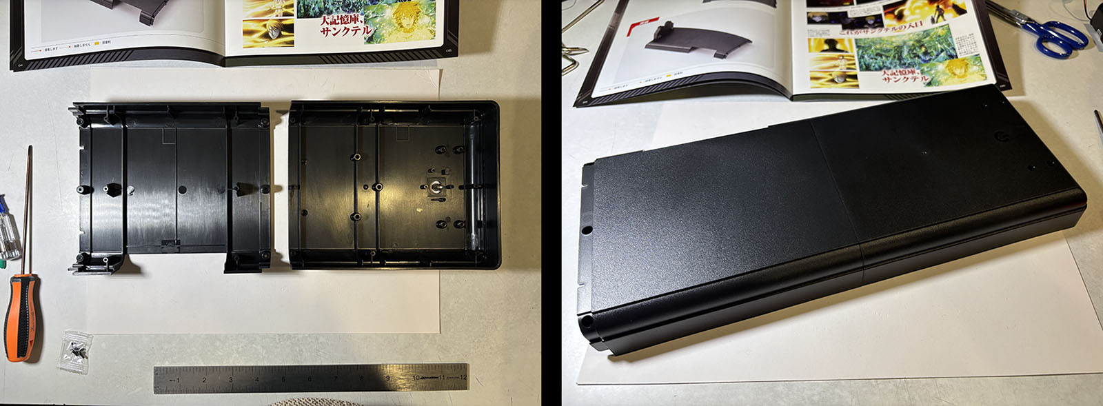
All we have to do this time is attach it to the first segment. I can just lay them flat on the table for this. That’s why I didn’t put the pillar on. It’s an unwelcome protrusion. If I were in charge, it would have been delivered last.
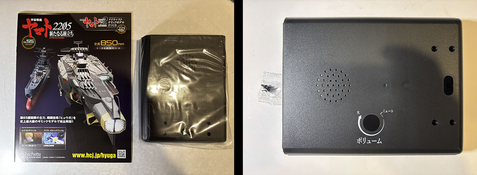
Vol. 55 has the third base segment. This part will contain the speaker and volume knob.
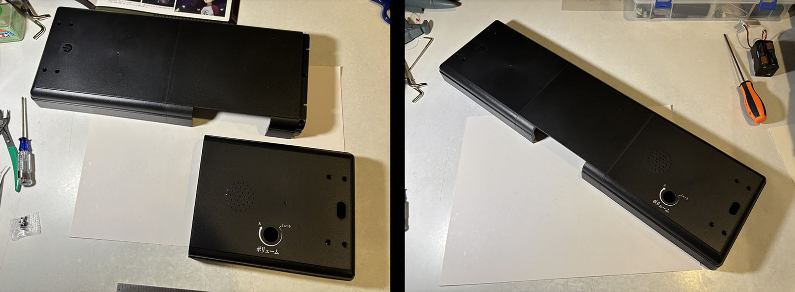
Again, since I didn’t put the pillar on yet, assembly is effortless. That’s the entire base, a little over 21″ long.
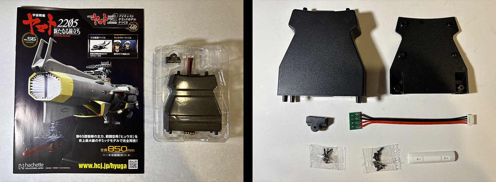
Vol. 56 gives us the other support pillar. It looks like the first one, but comes with some thick wires.
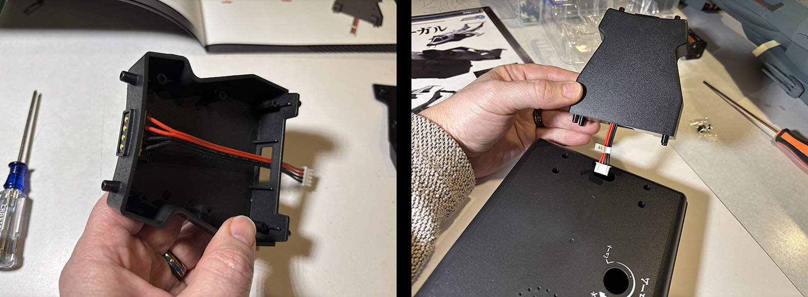
These are the wires that will deliver power to the ship, which sits on the connector you can see at the top. Then the other side goes over this and the pillar is complete. The instructions say to attach it to the base but we all know better don’t we? The instructions SHOULD say, “attach this to the base now if you want to make this operation awkward and uncomfortable.”
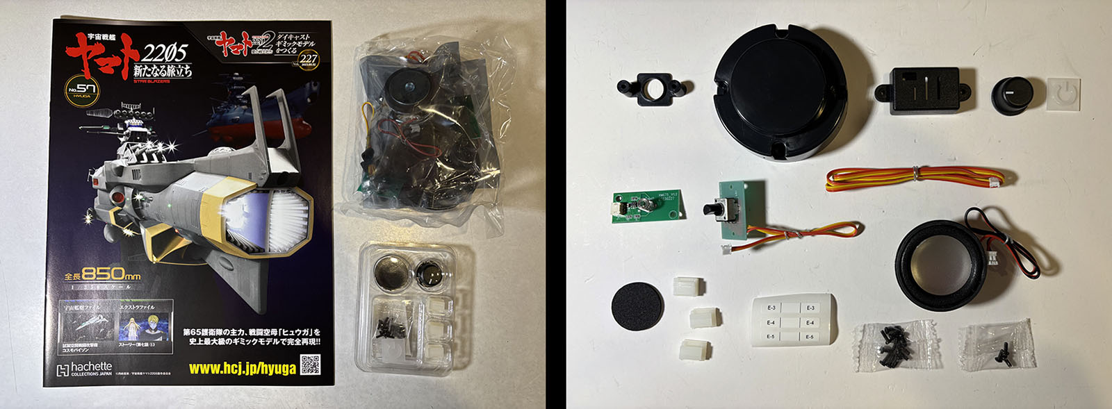
Vol. 57 is where we get to the real meat of this operation; the electronics.
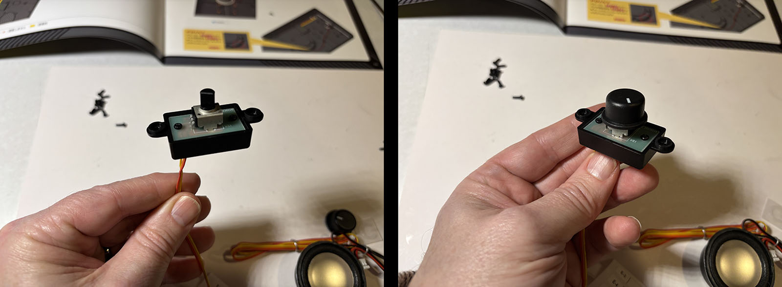
Step 1 is to assemble and install the volume knob. I assemble it, but installing it would just create another protrusion. And who needs that crap? Into the “later” pile it goes.
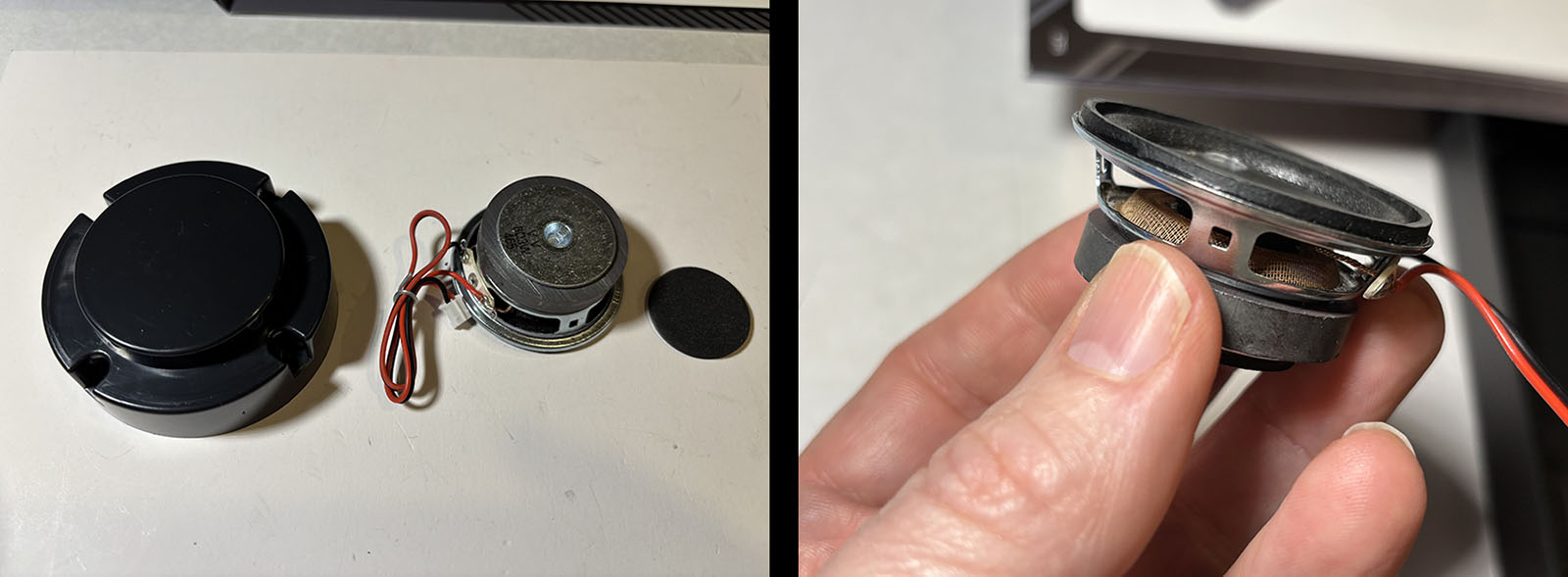
Step 2 is the speaker. I don’t know much about speaker technology, but this little guy is solid and heavy with a little shield on it. Nicely made. It’s the same type that went into the stands for Yamato and Andromeda, and it has better sound than you’d expect at this size.
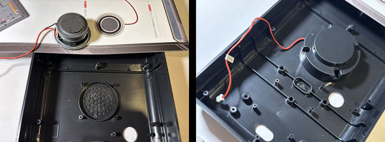
It goes into the base and the cover goes over it to hold it in place. Done.
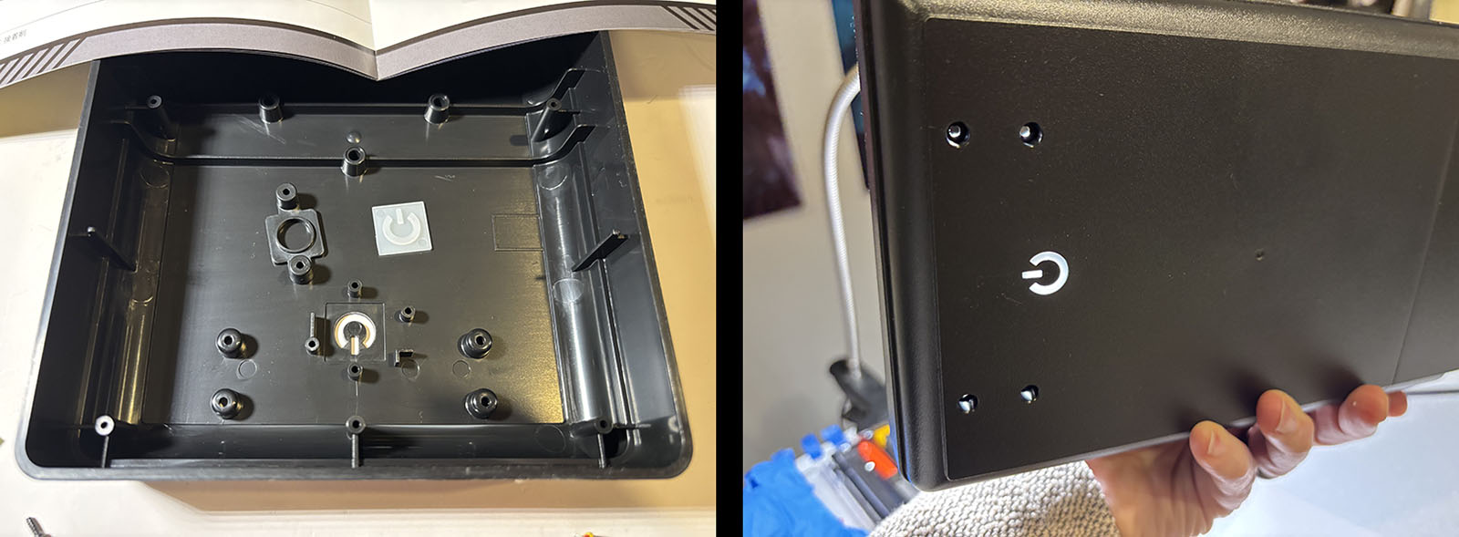
Step 3 is the power button. There are two small pieces that mount over the punchout. When they’re in place you see how they will convey light.
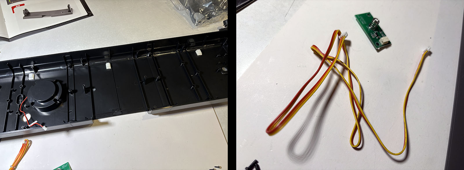
Left: three white clips get stuck into place along the back of the base.
Right: this wire will feed through those clips. The spring sensor will attach to one end.
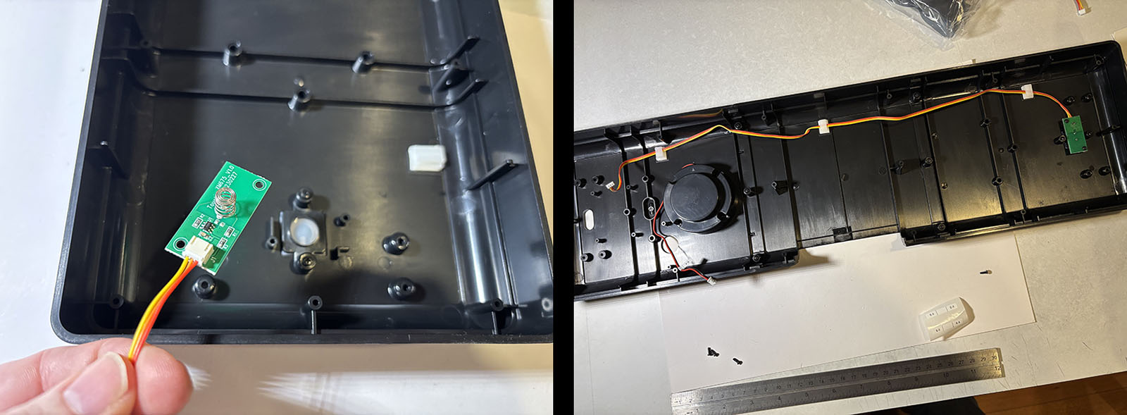
The spring sensor then attaches underneath the power button and the wires feed over to the other end of the stand where the power source will be. And that’s it for Vol. 57. What did we learn? Protrusions are not your friend.
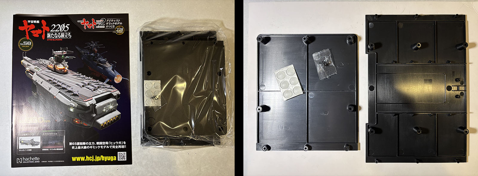
Vol. 58 drops down to the bottom of the display stand. In other words, the underside of the clamshell.
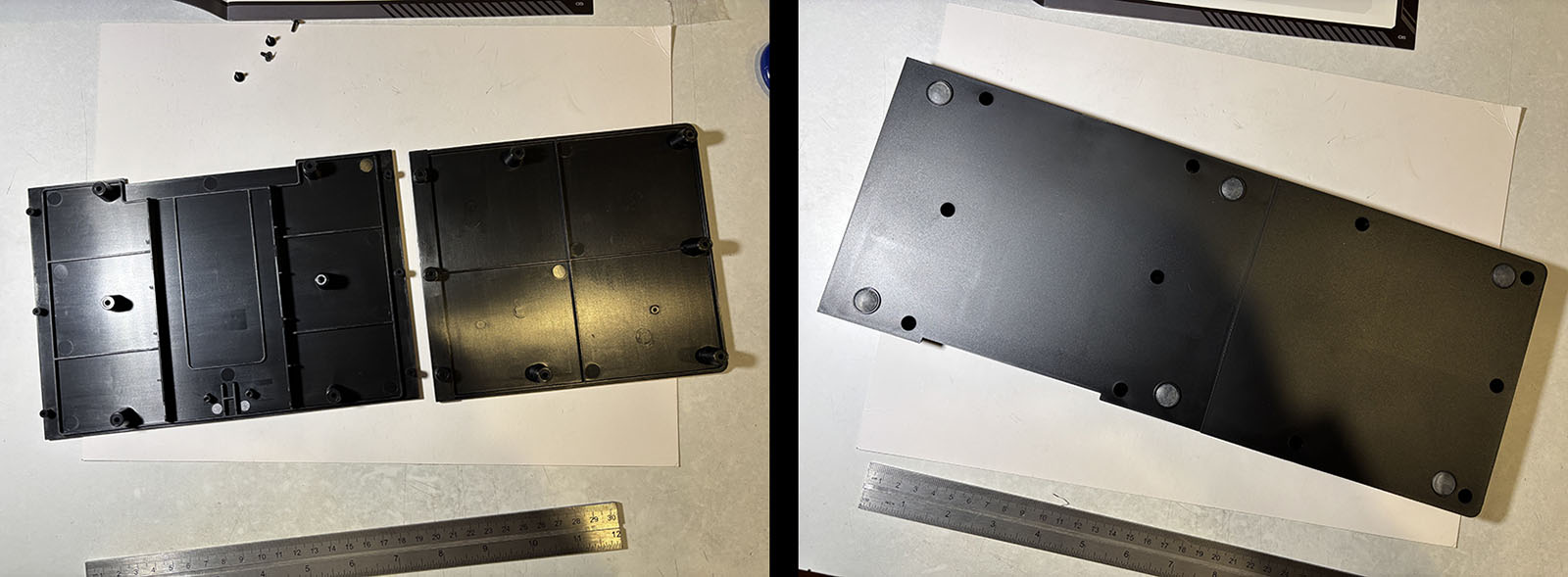
This one is dirt simple. Attach two panels together and put on the rubber feet. It barely takes a minute.
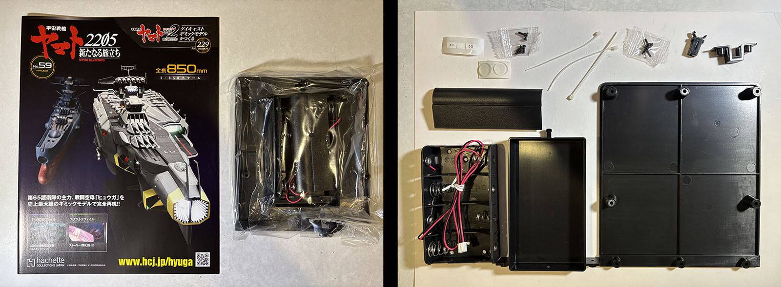
Vol. 59 already? This one gives us more parts for the display stand. It’s nearly all here now.
First, we attach the third and final section of the bottom panel. Add the last of the rubber feet and it’s finished.
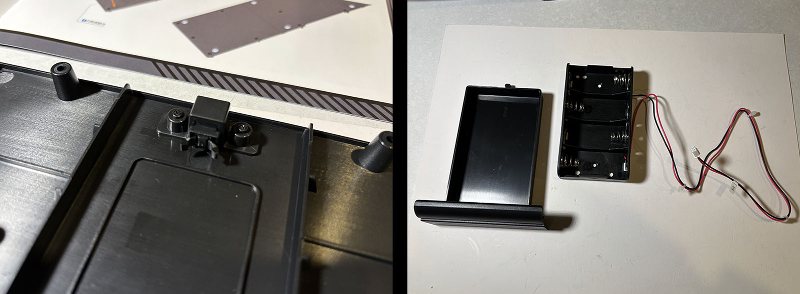
Second, a little clip attachment goes onto the center panel. This is the stopper for the battery drawer. The drawer itself is shown at right. All we do right now is put the “face” on the “drawer.” The battery housing is pre-fab, so it doesn’t need any work. It’s interesting to me that the nomenclature on it is all in English. These parts were all made in China, so this is probably the same battery housing that goes into a million products that all get sent to western markets.
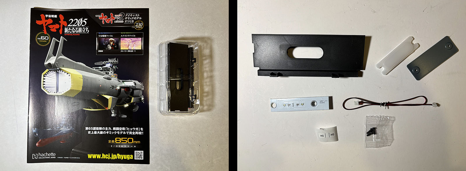
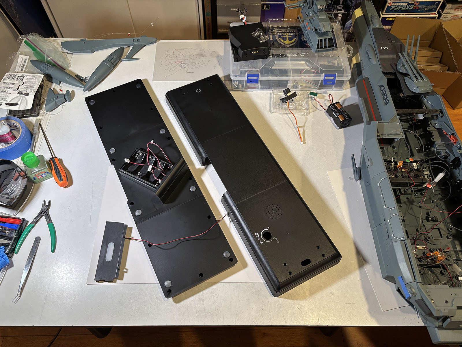
It will take only one more volume to let us complete the display stand, but for some weird reason, Vol. 60 veers away into a totally different place: the interior hangar.
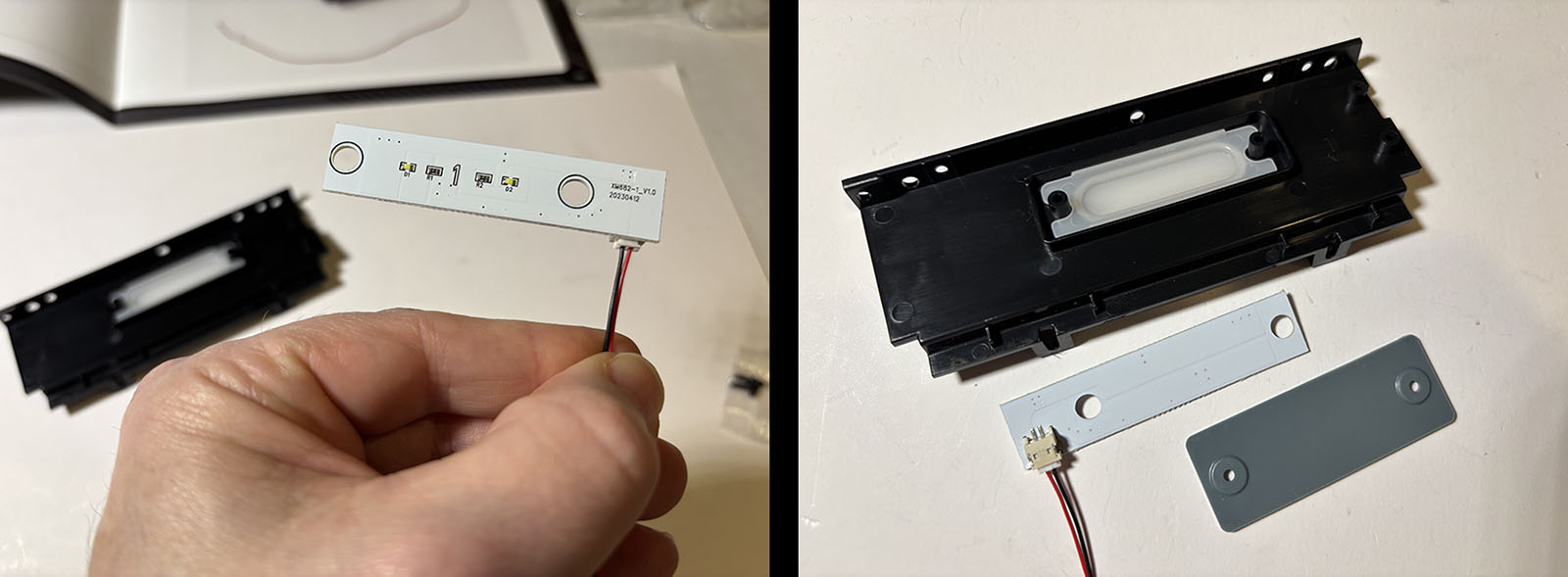
There are only a few pieces, and they’ll be sandwiched together to create one wall with a large light panel.
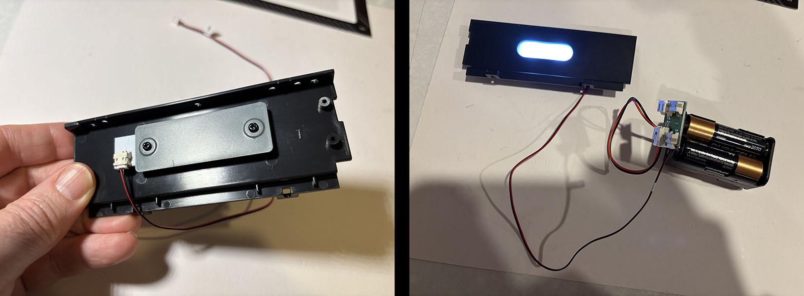
It goes together quickly and lights up just fine. But why did it show up now, just as we should be finishing up the stand? I can only guess that these decisions are driven by logistics and economics we can’t see from the consumer side. Maybe some element of the manufacturing process wouldn’t be in place at this particular time, or maybe there are limited windows for certain parts to be available at the best price. The strategy and planning for a product like this must be incredibly complex, dependent upon any number of factors. I’d like to know. It must be fascinating.
Anyway, there it is. Not a lot to show for this set, but we’re 60 volumes in with 20 to go. More like 15, since the last five are just devoted to aircraft. We still have the entire interior hangar to put together, then the top decks, various external bits, and the control box. It’s gonna get a lot busier before we’re done.