
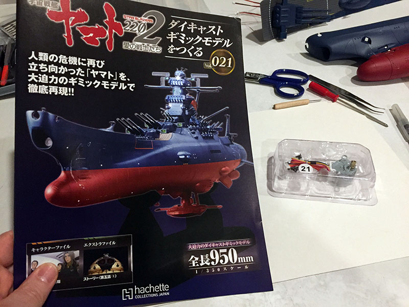
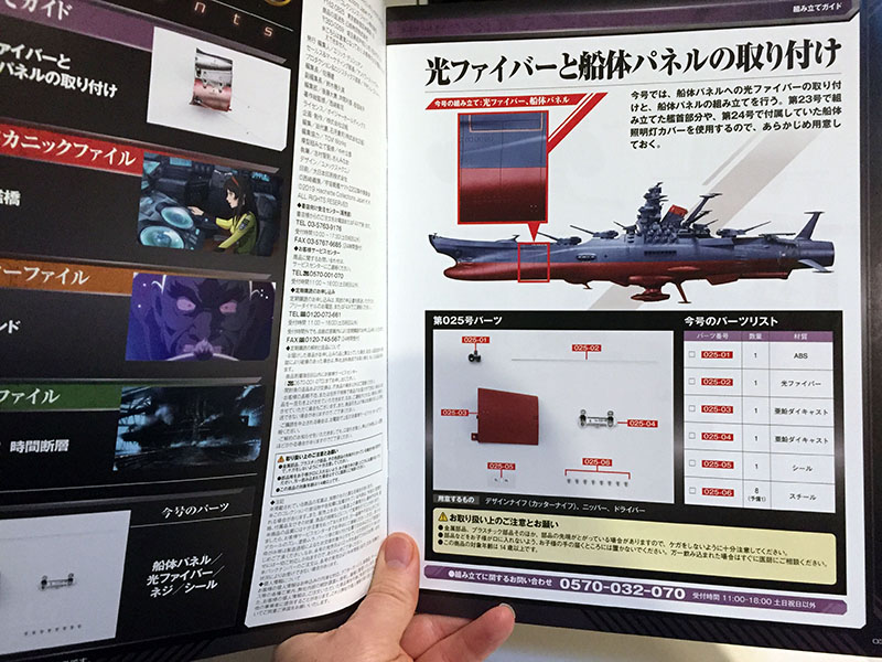
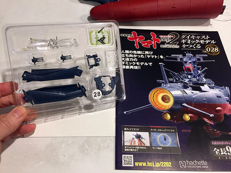
Volume 21 gives us a different kind of motor.
Parts relate to the rocket anchor and first turret.
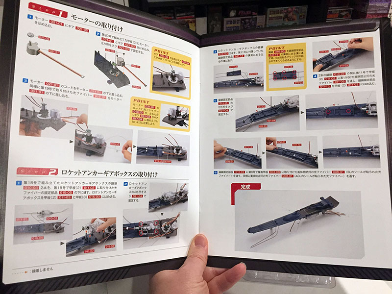
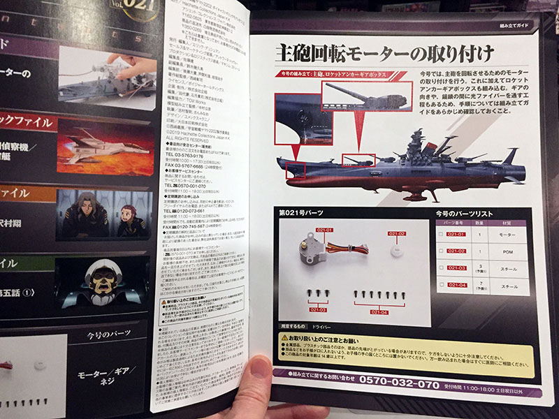
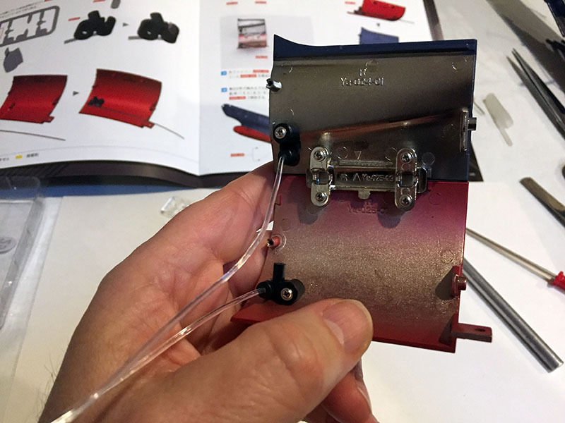
This is a 6 volt DC step motor that also attaches to the turret’s gear. Not sure quite what it does, but I’ll find out. Step 2 this time is to attach the gear box to the deck and install a plate that creates a path for the rocket anchor chains.
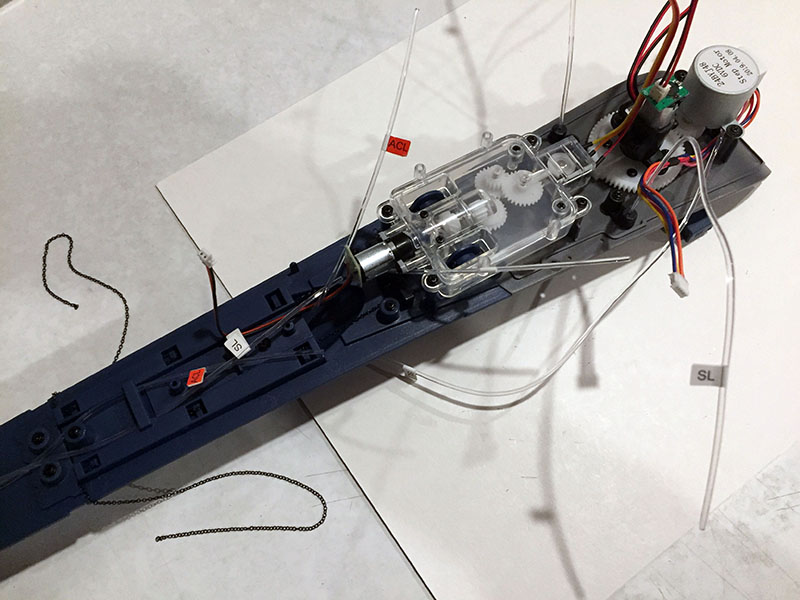
Getting that thing on while dodging fibers and not dropping the chains was an exercise in acrobatics. Just one of many challenges that keeps this project interesting. Every time I conquer one of them, I feel like my “life bar” just got an extension.
Next four volumes, ahoy!
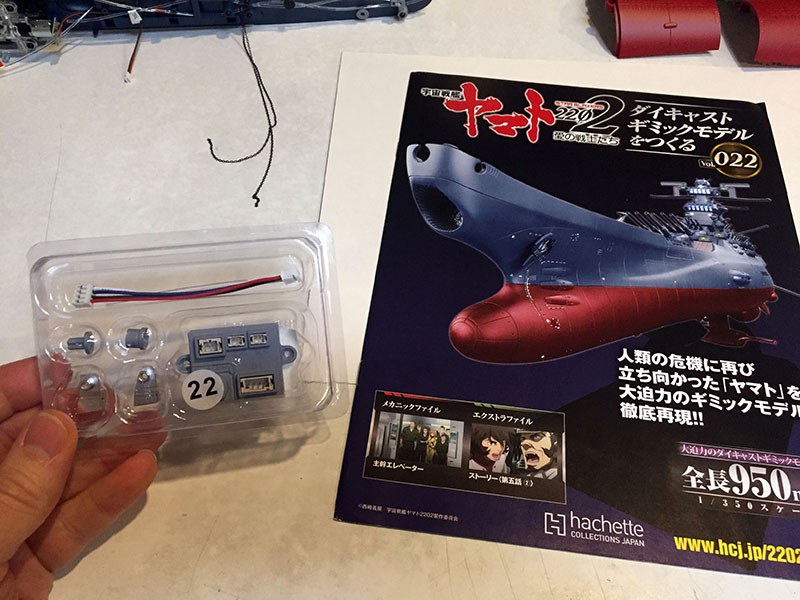
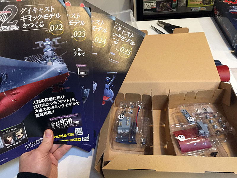
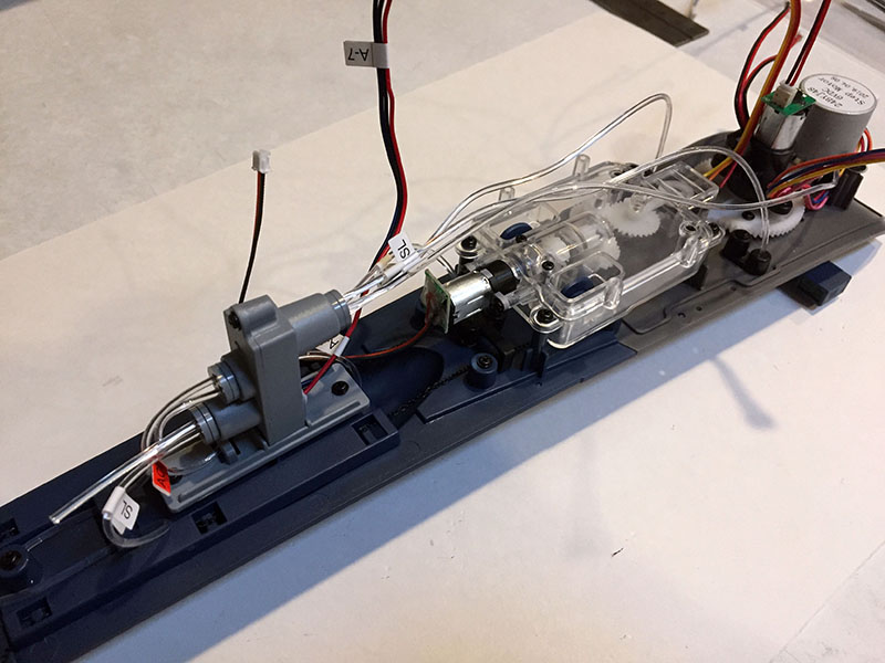
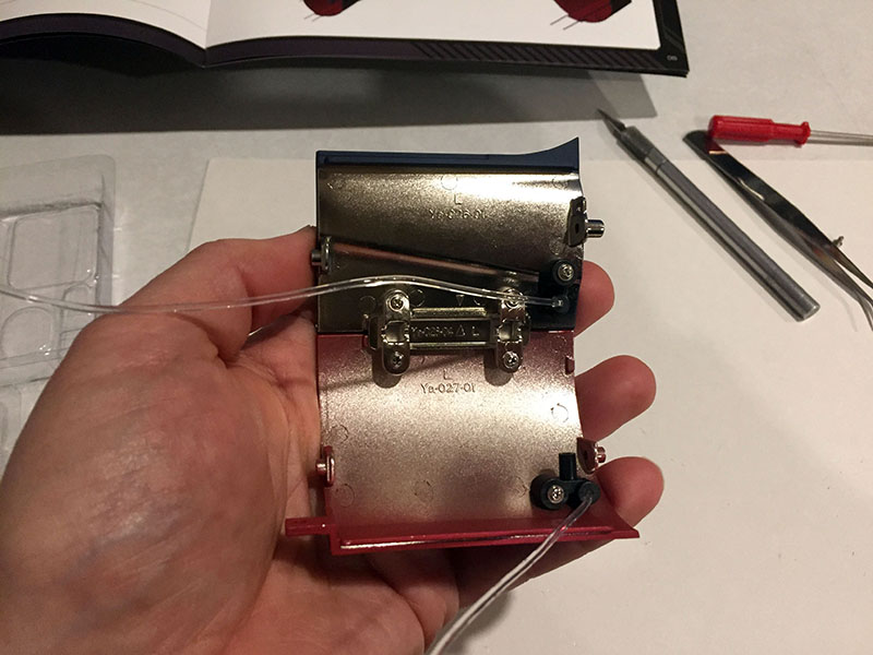
Volume 22 gives us our first junction box. Sexy!
It will go into the forward section.
Lots of fiber and wire work this time.
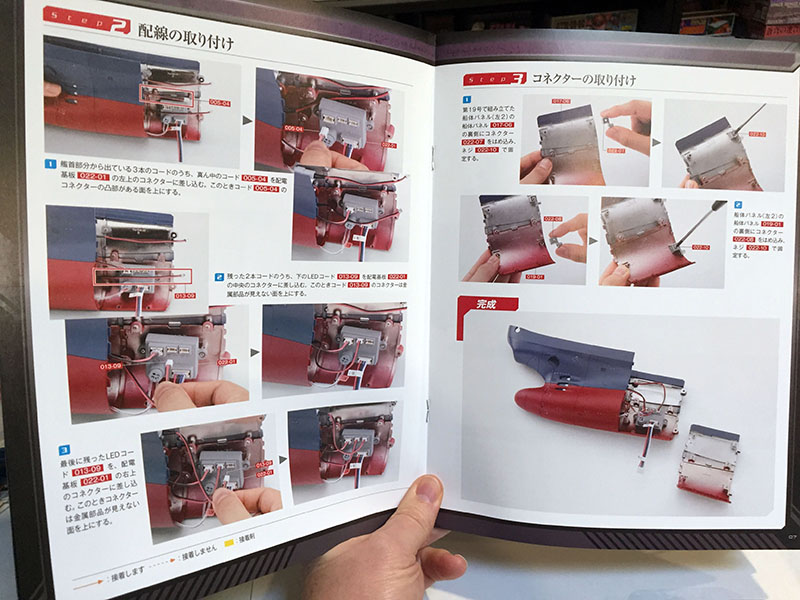
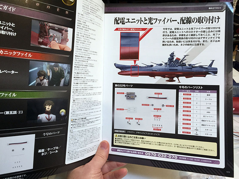
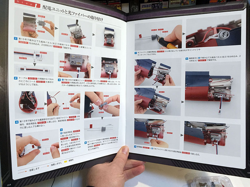
Four pages of instructions. That’s a record. Part of the challenge is plugging wires into the junction box in the right sequence, and making sure they’re not impeding anything else.
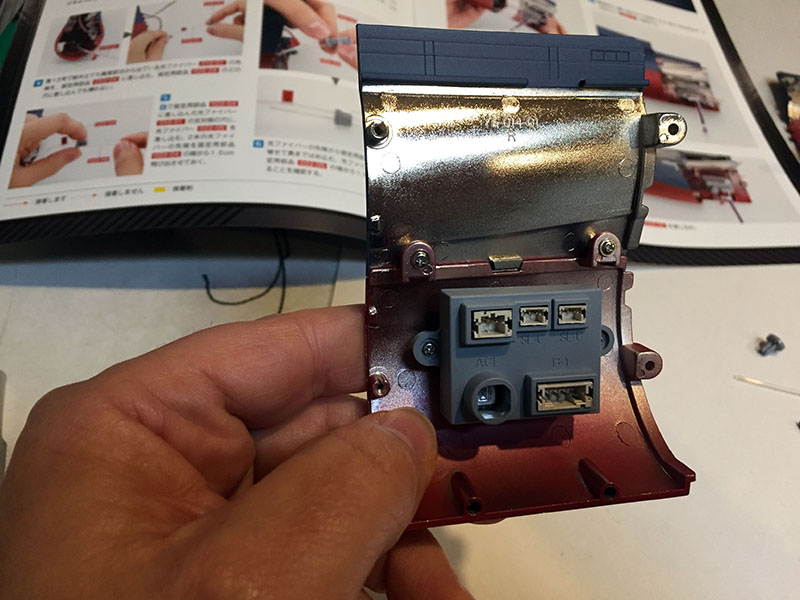
Junction box in place.
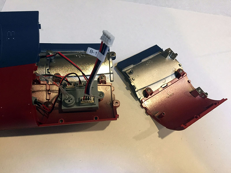
And done. This is where all the wires and fibers I’ve installed so far got locked down. The new “B-1” wire will lead to a power source. Believe me, this is all harder than it looks.
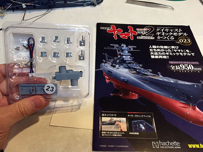
More internal parts in Volume 23. I guess someone who just wanted to see the ship get done could skip a lot of these, but that sure would be a waste of money.
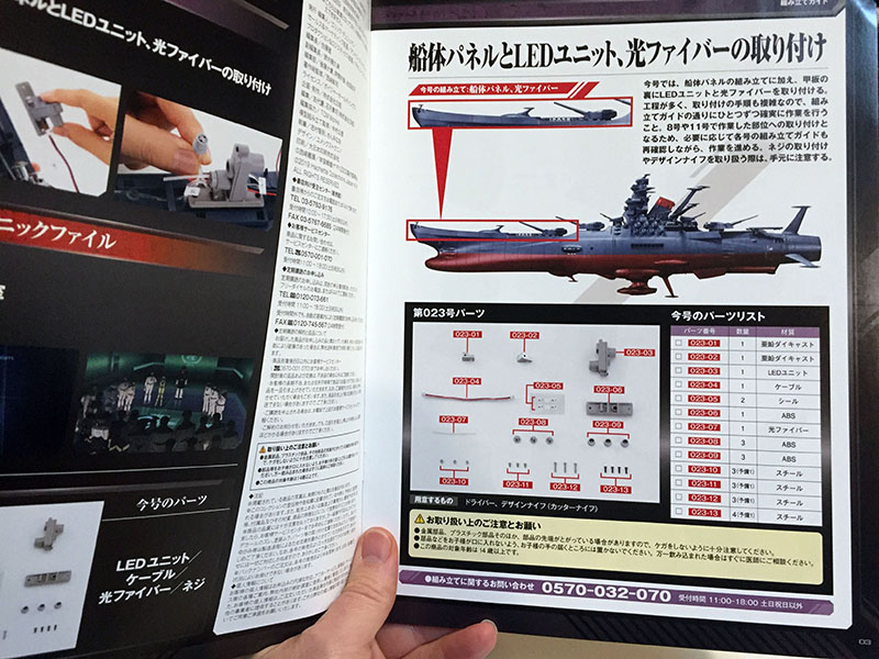
More stuff involving the forward deck.
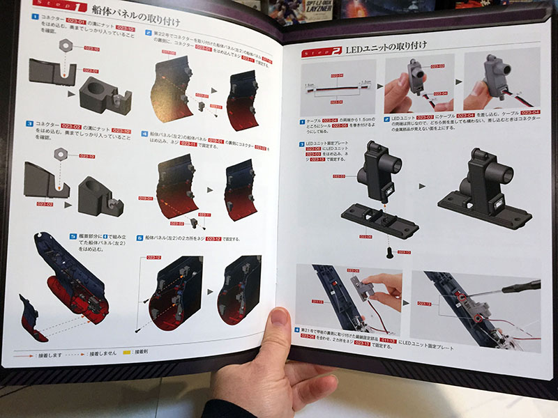
Two more hull plates that came in an earlier volume now get the last of their hardware, and we’ll add an LED unit to the deck.
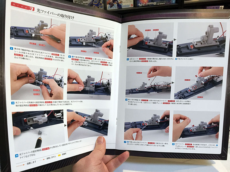
Several fiber cables have been pointing every which way. Now they’ll be secured.
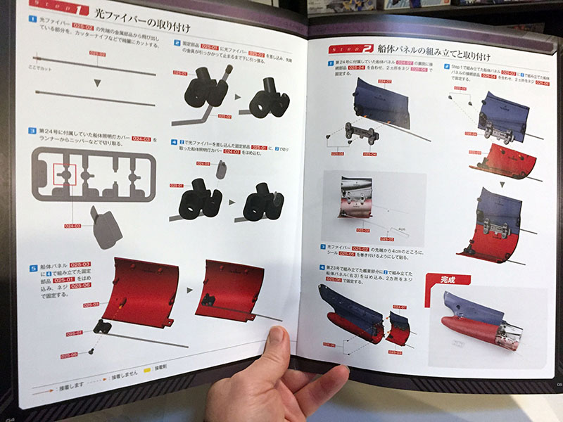
SIX pages of instructions this time. Several complex steps to cover.
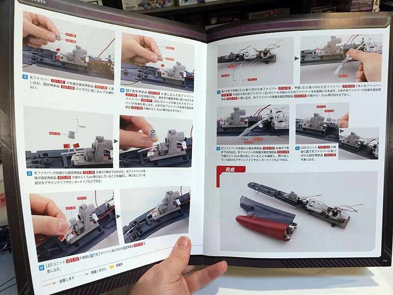
There it is. All the fibers are now tied down to their light sources.
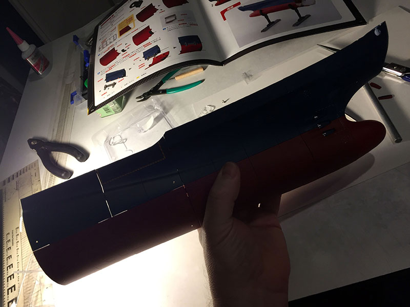
And another section of the hull is complete. It’s now approaching 10 inches long.
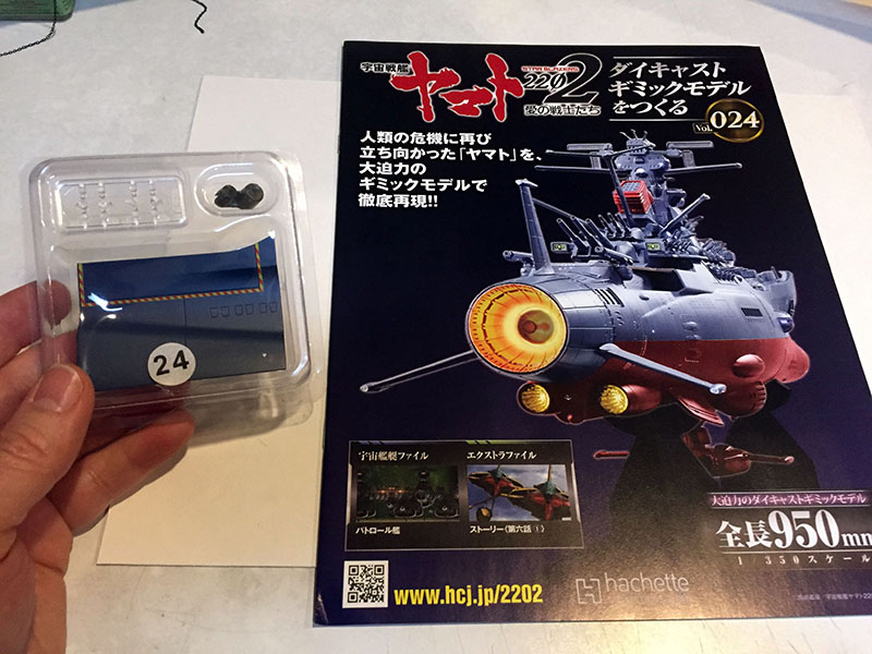
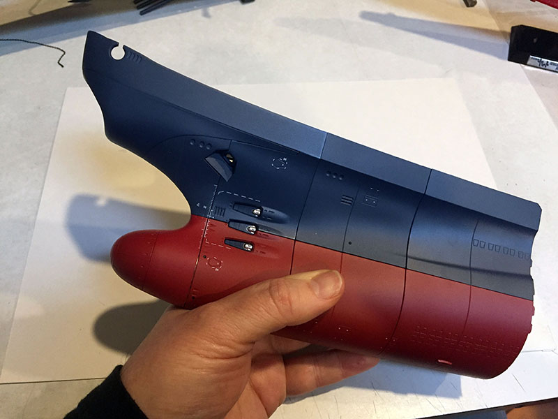
Volume 24 looks like a simple one. Good, I can use a break.
Just a new hull plate this time.
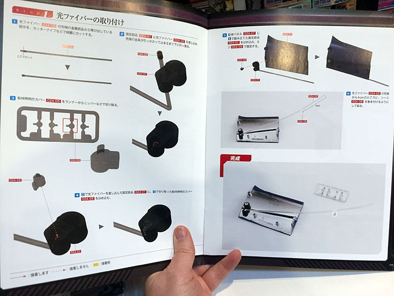
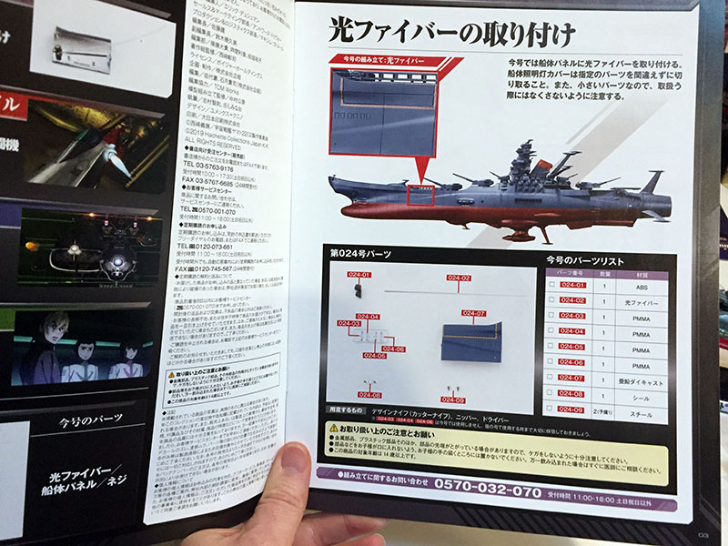
Back down to just two pages of instructions. Thank you.
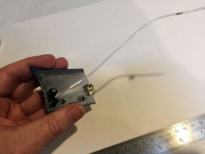
That’s it. Just one light attached to one hull plate.
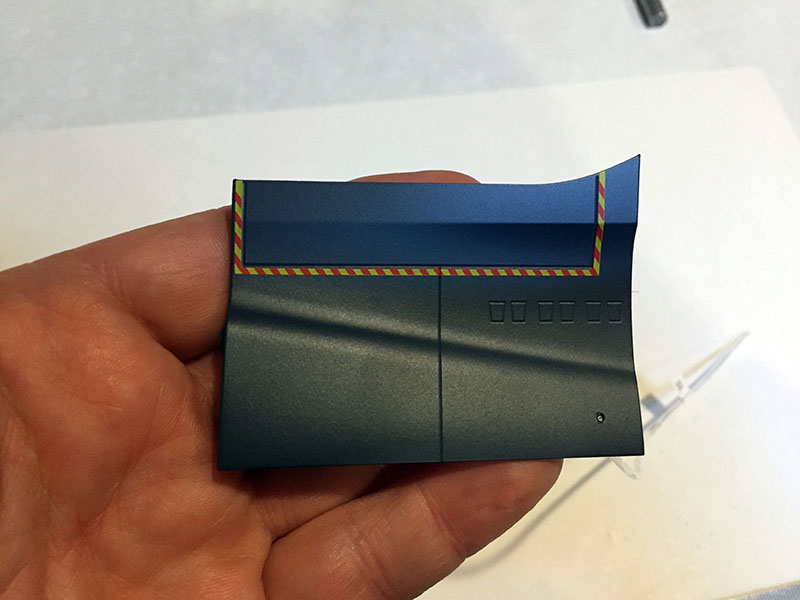
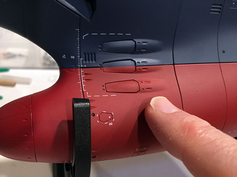
Here’s the other side of that plate. I have no idea how you print something that precise on a piece of metal.
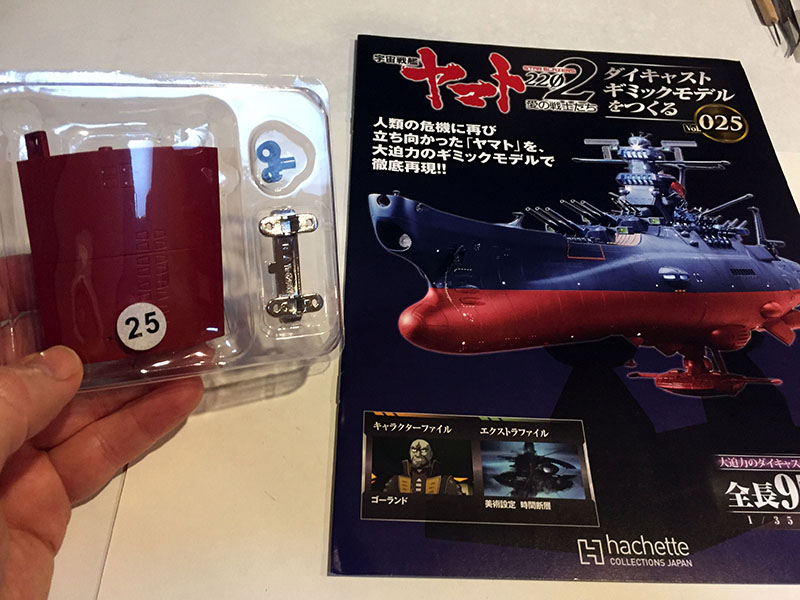
Volume 25, another hull plate.
This one will attach to the last one.
Yep. Stick a light on it, bracket them together, attach them to the ship. Easy.
Bracketed together. Now just attach them to the ship…
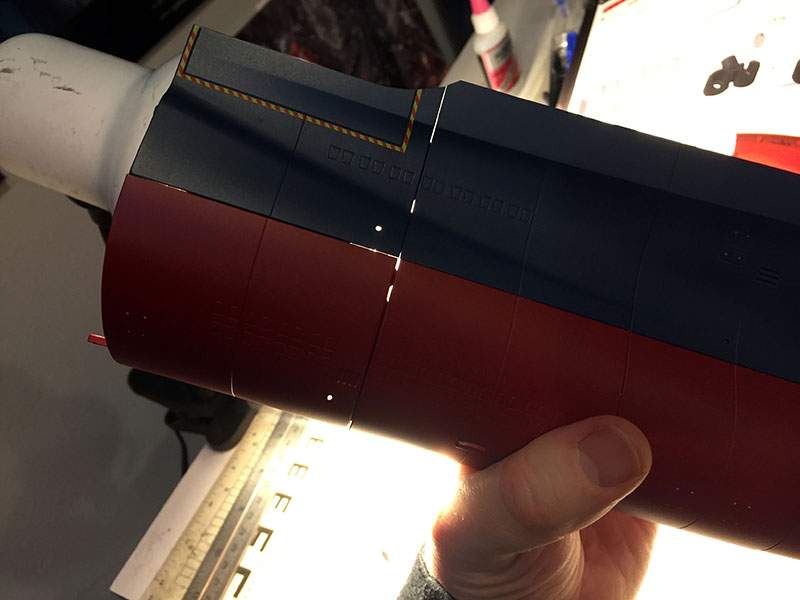
…and here it is. This is what I’d been hearing about in my research. Hull gaps. These pieces don’t fit tightly enough to keep light from bleeding through. I don’t know if that will be a problem once the hull is all closed up, but it sure looks like a problem now. I could maybe fill it with aluminum foil inside, but we’ll see…
Anyway, that takes care of Volume 25.

Next set of four. Should I? I really need to start writing the latest 2205 report…
Ah, what the hell. It’s all for the same cause, right?
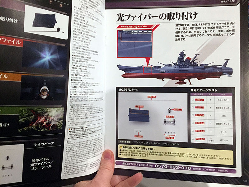
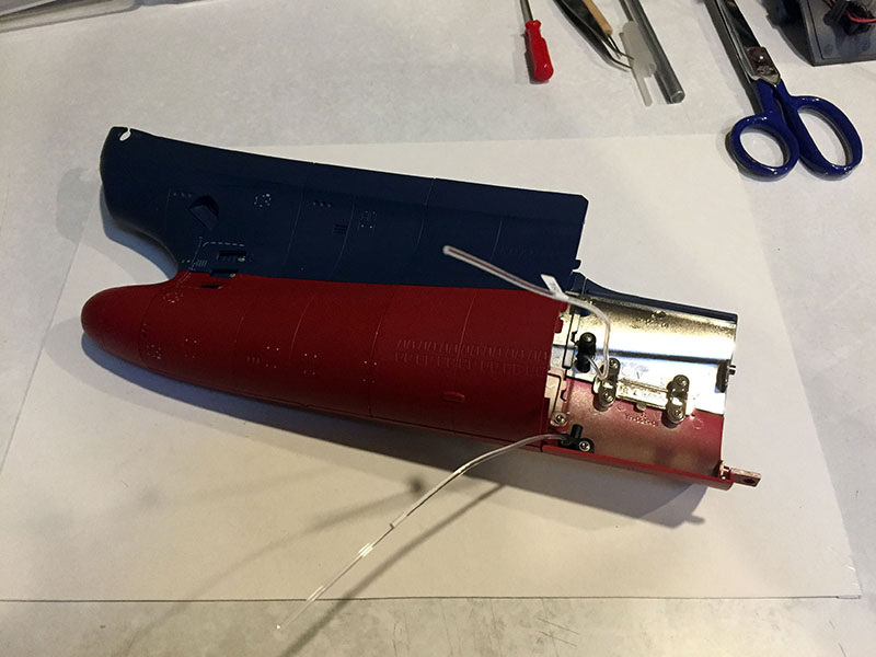
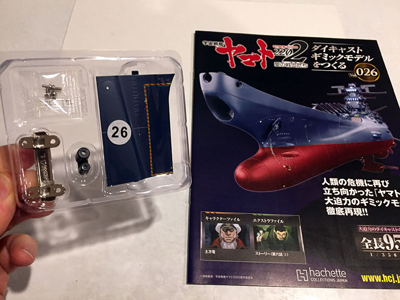
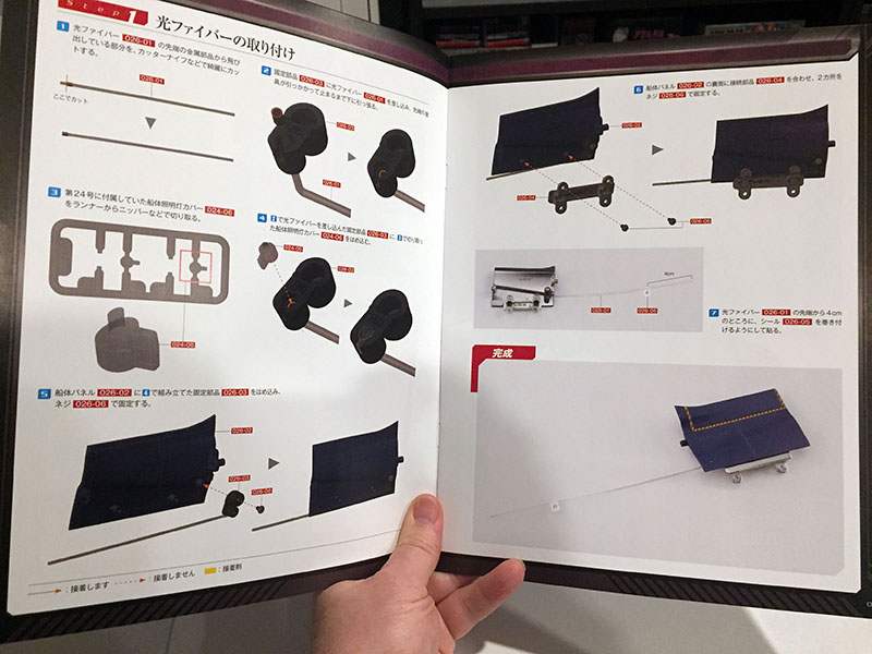
Volume 26 starts us on the same section of hull for the other side of the ship.
Yep, been there.
Done that.
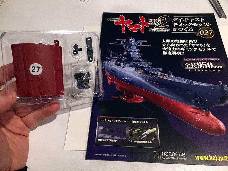
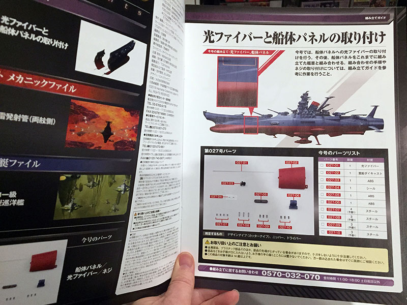
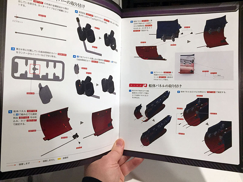
Volume 27 looks familiar as well.
Mirrored parts from Volume 25.
This time we’ll stick them on the port side.
And then we anchor down this hunk of hull in the lower center. On the right you see the “magazine” portion of the magazine. The pages following the instructions are fantastic, and will be posted in some future update.
Hull plates lit and bracketed.
The ship is now the length of Banpresto’s “display model,” which is 11 inches long. Also, it weighs a little over two pounds. That doesn’t sound like a lot until you remember that most model kits weight practically nothing. Or until you try to lose two pounds.
Okay, one more volume for today, then I really need to get working on that report.
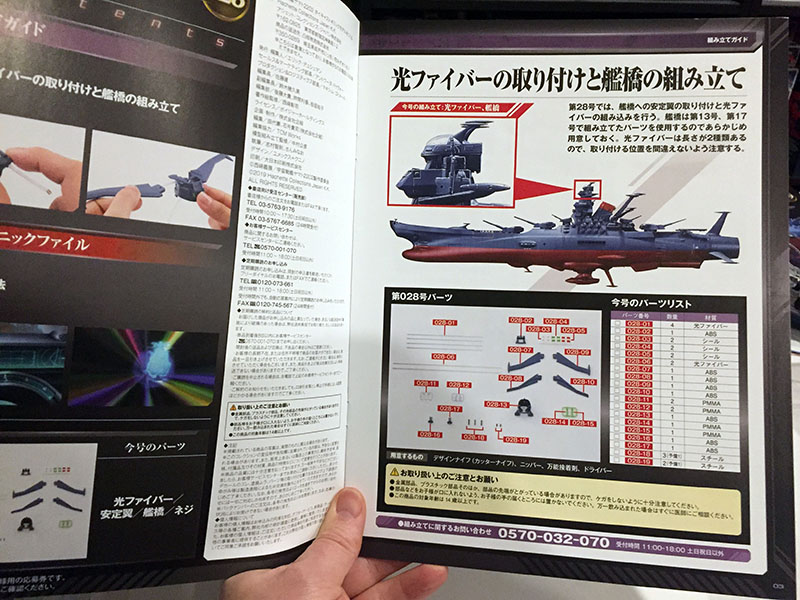
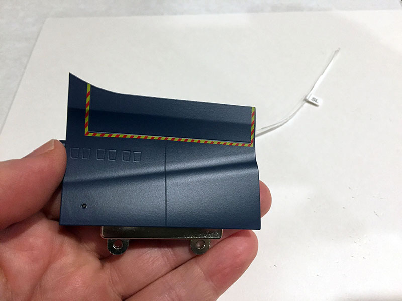
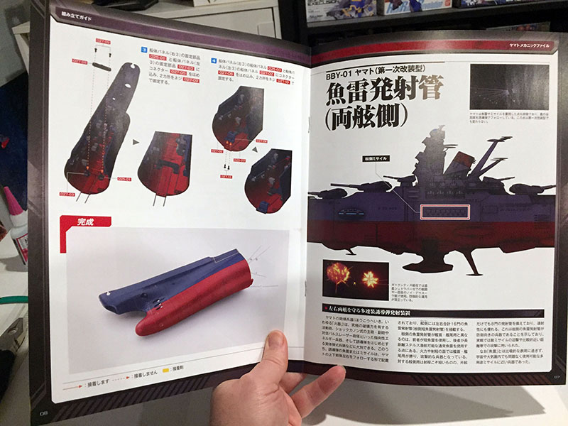
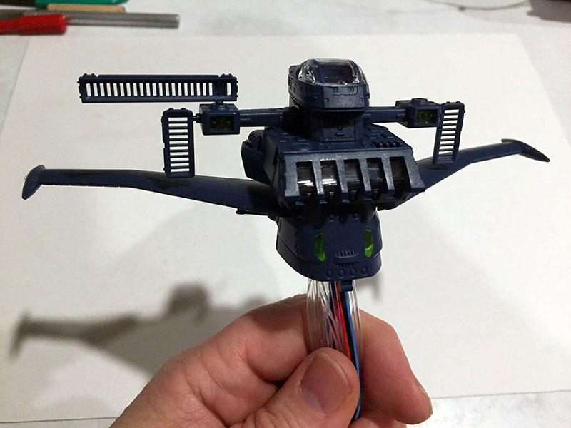
We’re back to the bridge tower for this one.
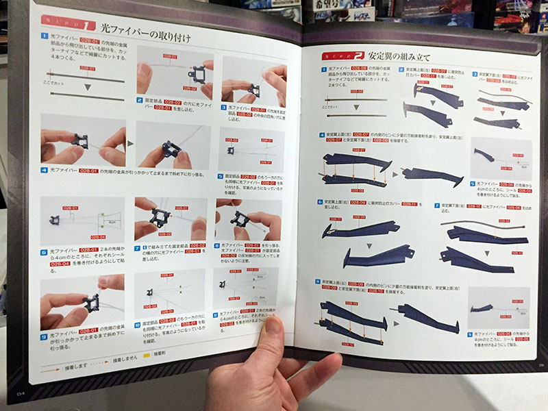
We’re installing a bunch of fibers, including one on each wing. There’s a light on each wingtip.
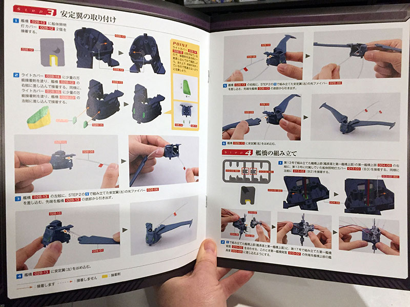
We’re also doing some intricate work on the tower segment just below the first bridge.
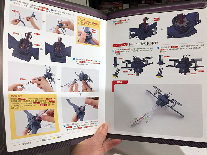
When we’re done, it will look like this.
OH MY GOD was this a nightmare. If I’d known, I would have stopped with Volume 27.
The wings were a major challenge. The instructions made it look like the fiber cables would obediently sit inside their channel while you glued the wings together, but all they wanted to do was pop out and fly away. I consulted two separate online sources that both said to just glue the monsters down. I was hesitant, because glue can melt these fibers, but there was no other way to go if I wanted those lights to work. Worst case scenario was that they just wouldn’t work. So I went ahead and did it. They seem OK. I held the other end of the fibers up to a light bulb and they transmit fine.
As you can see, one of the sensor grills came off. I knew I should have put them on later. Fortunately, it didn’t break off, it just came out of its socket. Easy to replace later.
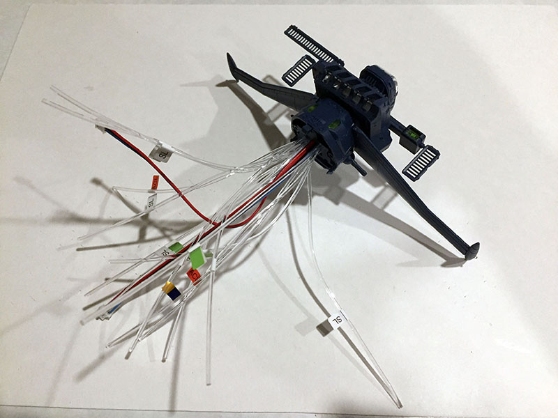
Then the OTHER challenge; feeding all that fiber spaghetti through not just one, but TWO internal apertures. When I saw what the instructions were calling for, it was like “what?” and then “You want me to WHAT???” It took a few tries and some very careful threading. Also, one of the metal cuffs popped off the end of a fiber and I didn’t have a spare for it, but in the end it seemed to still work. With something this expensive, everything that doesn’t go precisely to plan is cause for anxiety.
The selling point of this model is how big it is, but the dichotomy is that microscopic surgery is often required to fit it all together. And I ain’t Ant-Man.
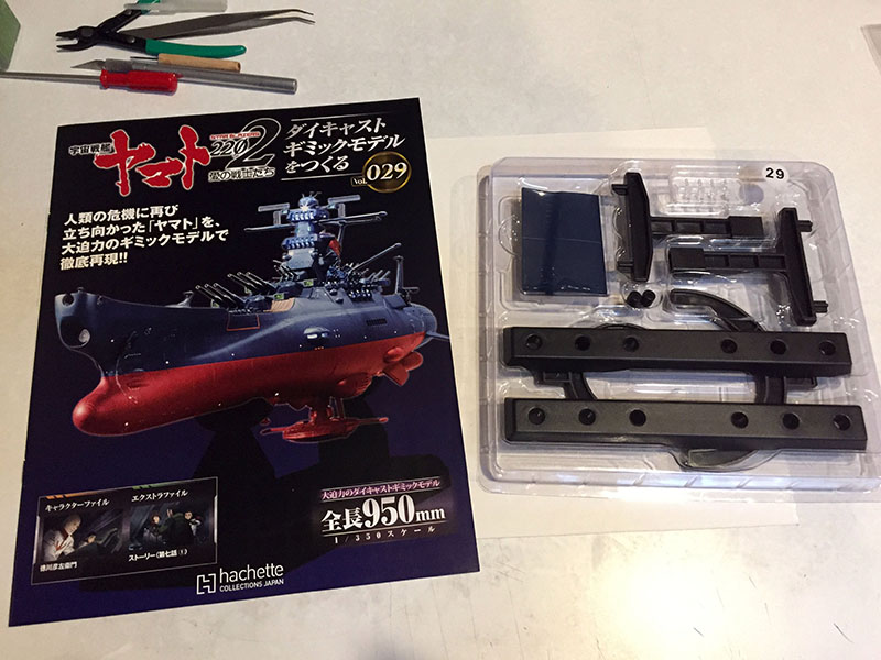
One pattern I appreciate here is that a very complex volume is often followed by a very simple one. Much less to do in Volume 29.
We’re approaching the midship area now.
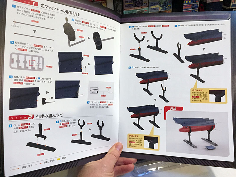
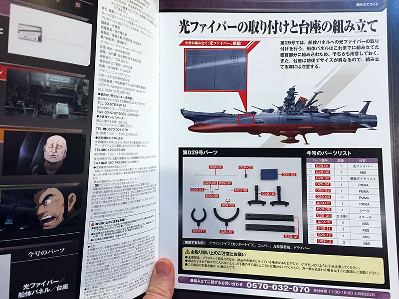
Instructions can be contained on just two pages. In addition to a new hull plate (with just one light) we’ve got a temporary stand to put together.
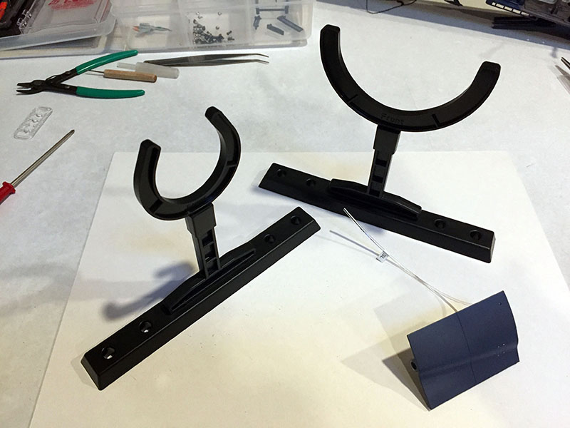
Done in mere minutes. The stand parts just snap together.
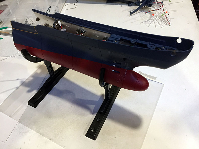
And now the hull is up off the tabletop. However, the stand is just as wobbly as it looks. That’s why it’s temporary.
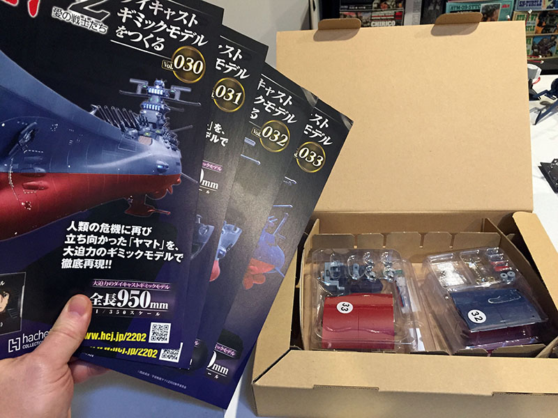
Here’s our next batch of four.
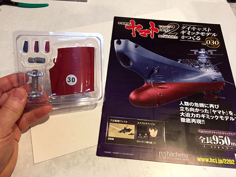
Volume 30 is another simple one.
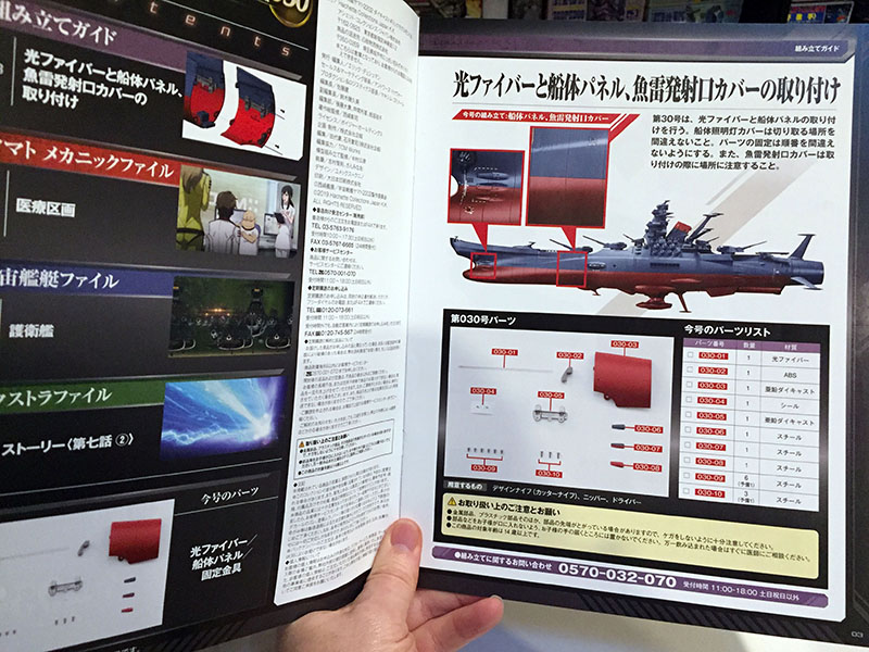
Another hull plate and something to do with the bow torpedo tubes.
Just two pages of instructions again. This will go quickly.
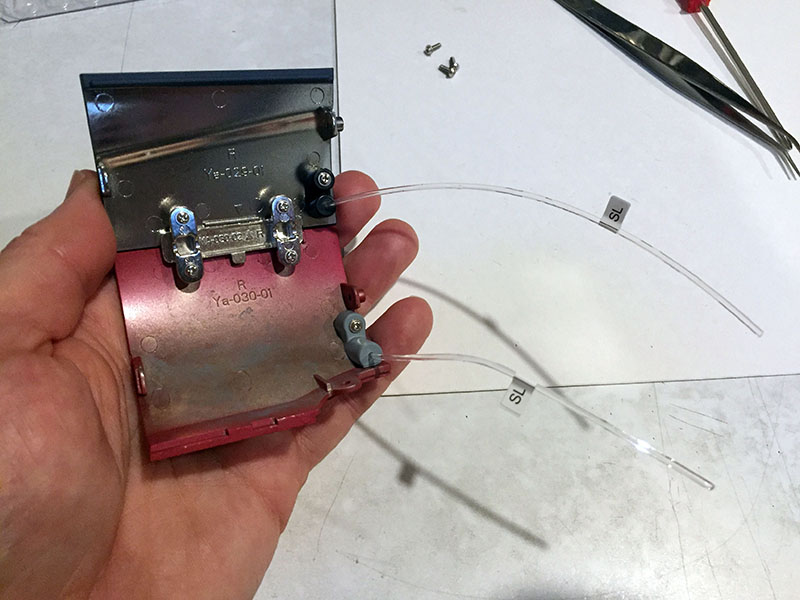
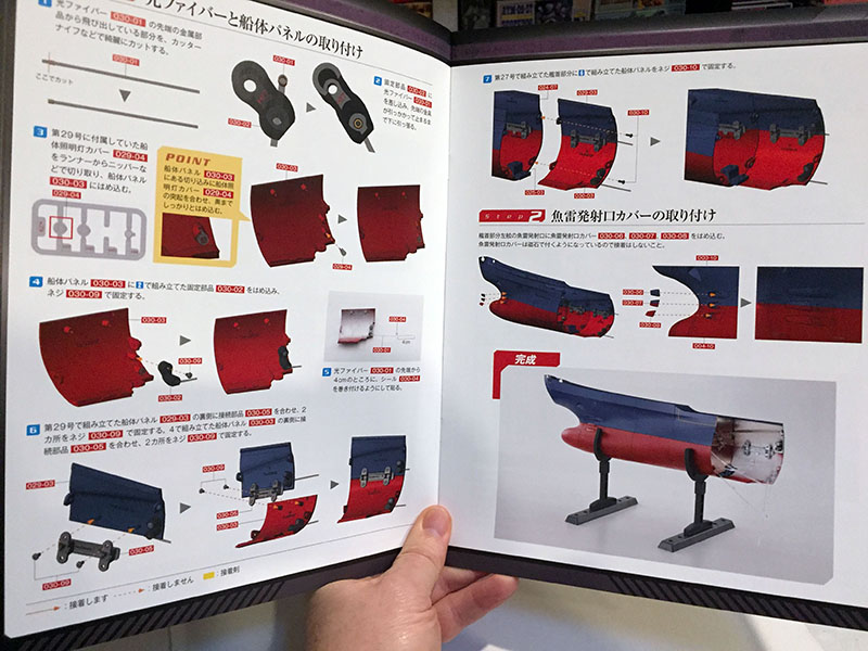
Step one done; two hull plates bracketed together.
Unfortunately, the light leak problem continues.

Step two is as simple as it gets; attach the covers to the torpedo tubes. Remember, there are mighty little magnets glued to the interior.
…and they work! They’re not foolproof, though. It doesn’t take much to dislodge these covers. They don’t fall off, but they can easily be pushed around. After I made this discovery, I put them aside until all the manhandling is over with. (There’s a LOT of manhandling coming up.)
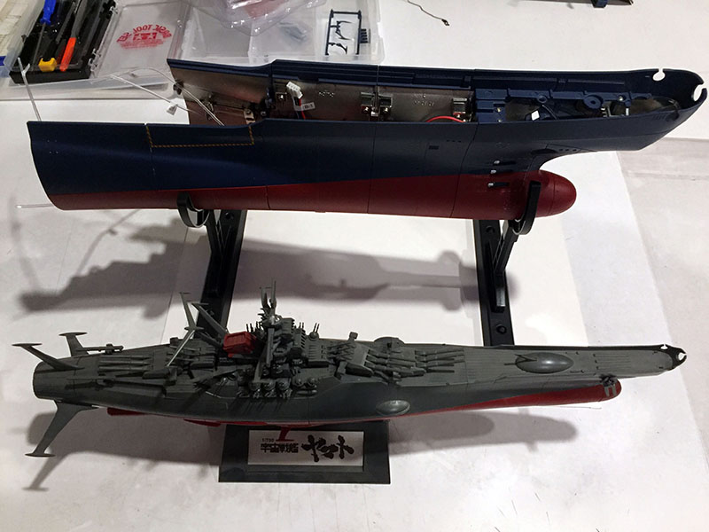
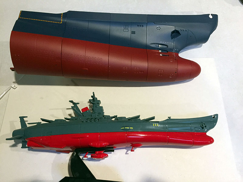
The new hull plates boost the length to 15″, which is an exact match for a 1/700 scale model kit. And we’re not even halfway yet.
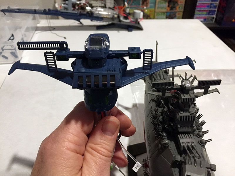
Another scale reference: the completed section of the bridge tower right next to its 1/700 scale predecessor. Impressive. Most impressive.