

Here we go with Volume 31. One of the reasons I waited until all volumes were in before starting is represented here; this is not a perfect product. Hachette made a few mistakes along the way. In this case, there was an error in this instruction manual that got addressed in Volume 38. You’ll see.
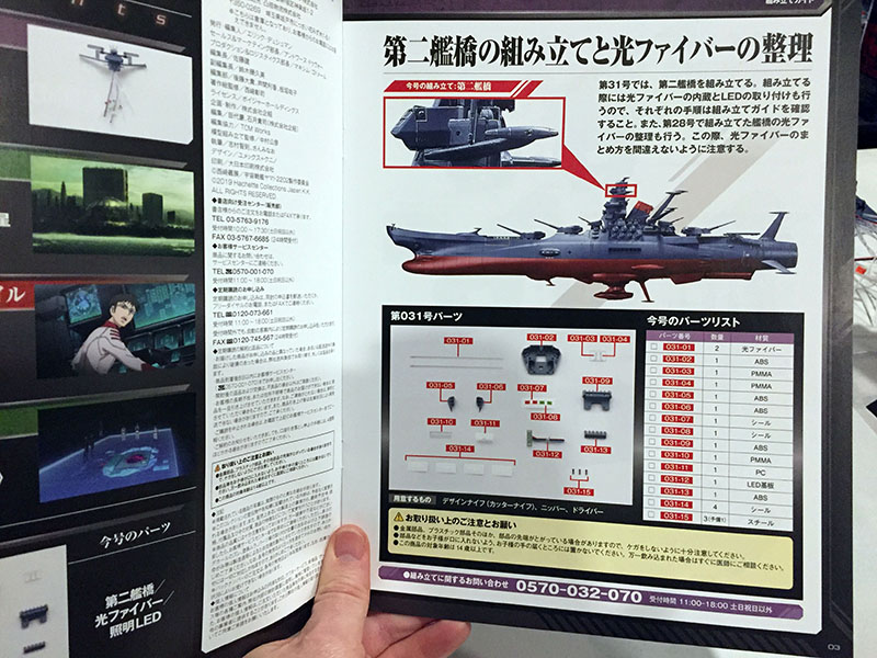
Back to the bridge tower.
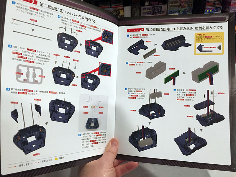
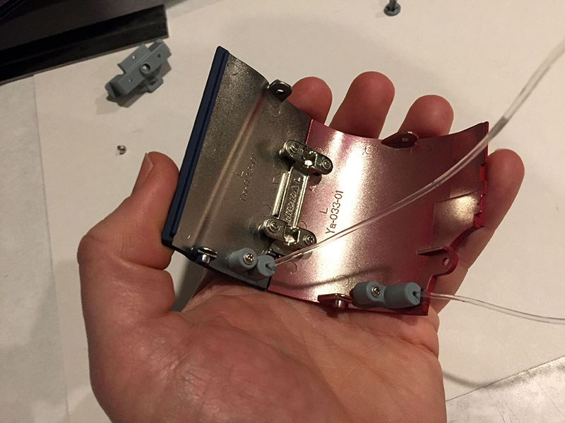
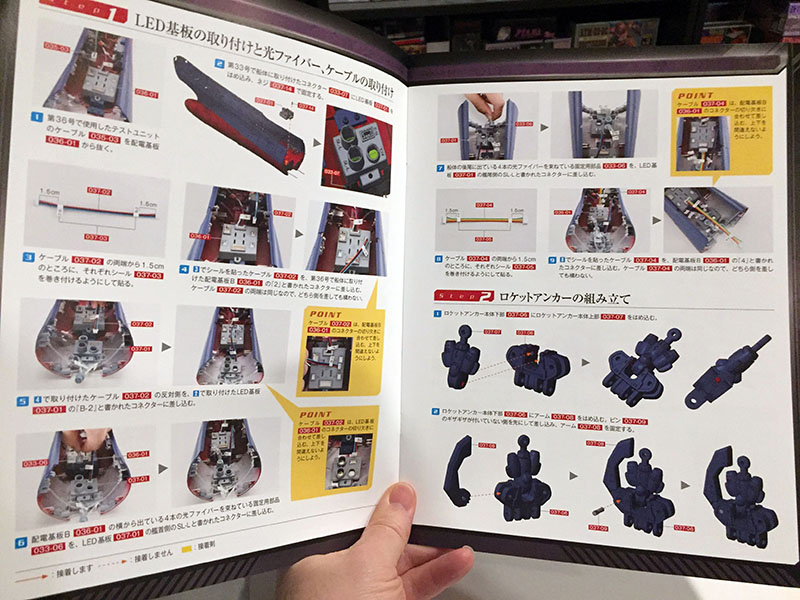
The task this time is to assemble the second bridge.
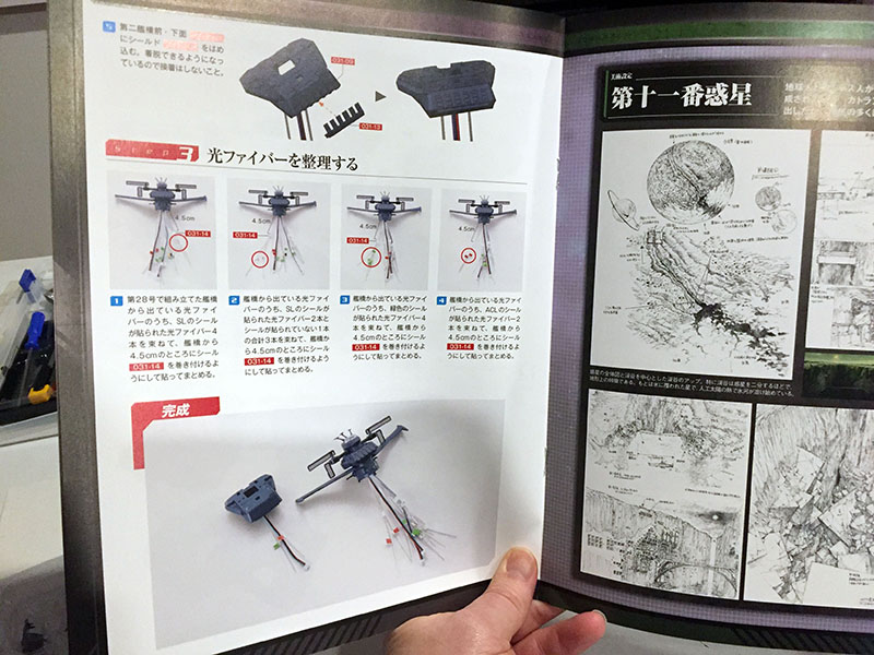
…and then return to the spaghetti of fibers and wires descending from the first bridge. This is where the error appeared in the text. We’re supposed to bundle some of those cables together in a very specific way.
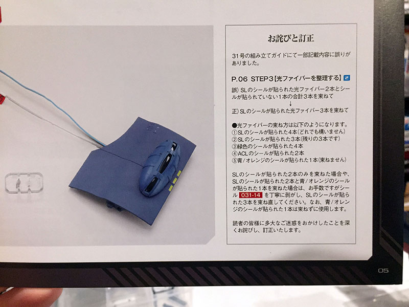
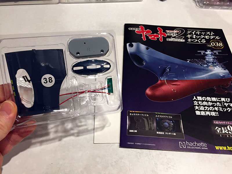
Looking ahead to Volume 38, here’s the correction. I applied the same translation process I use on Cosmo DNA articles (scanning, OCR, software, editing) and got all the information I needed. The mistake was quite simple; they said to bundle three specific fibers instead of four. If you followed their initial instructions, you’d have to undo the bundle of three and add the fourth.
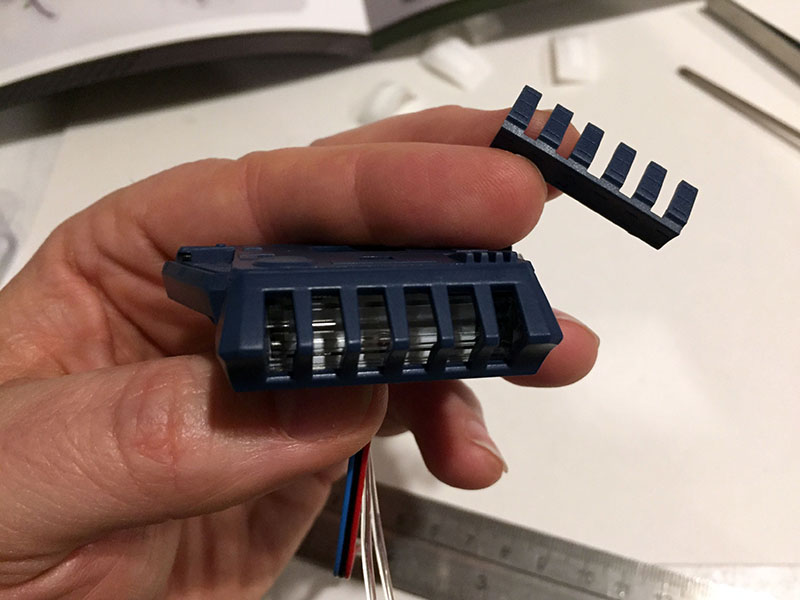
Anyway, second bridge assembly was easy. Like the first bridge, it comes with optional safety shutters.
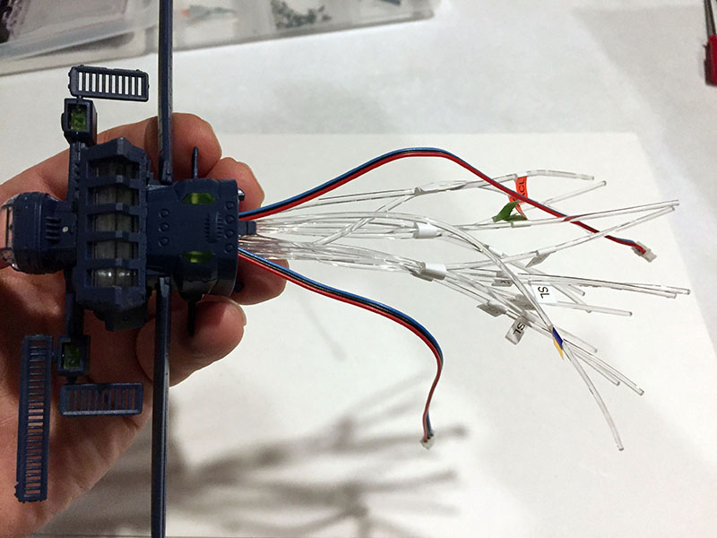
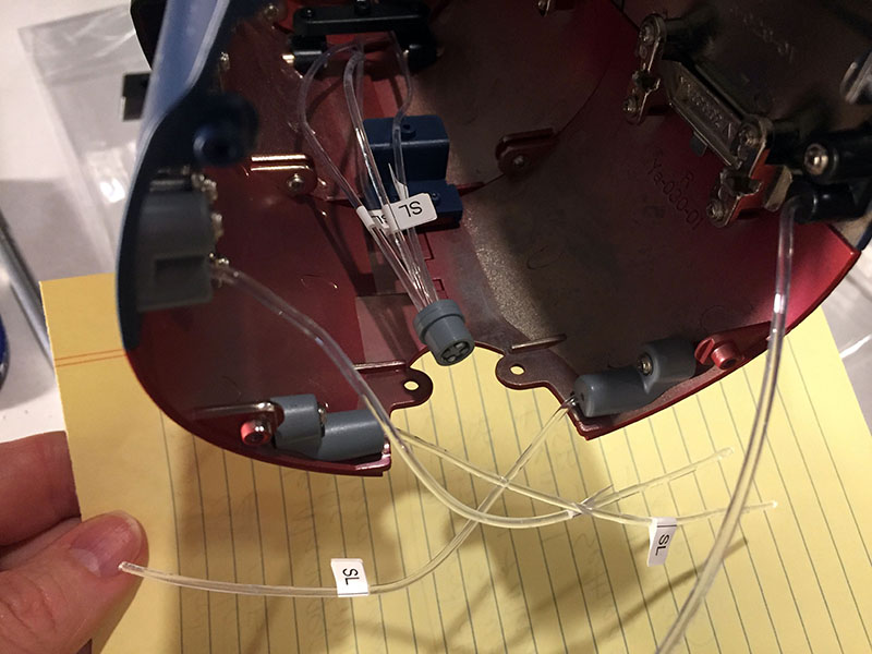
And here’s the end result of the fiber-bundling. Believe it or not, this makes things much easier to grapple with.
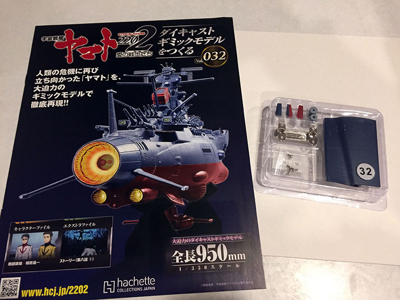
Here comes Volume 32.
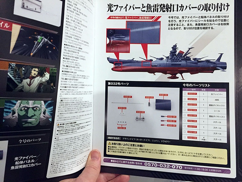
This stuff looks familiar. Now we’re just moving to the other side of the ship.
One new hull plate and the other three torpedo covers. Simple enough.
Done…
…and done.
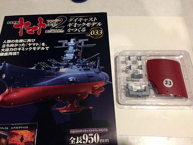
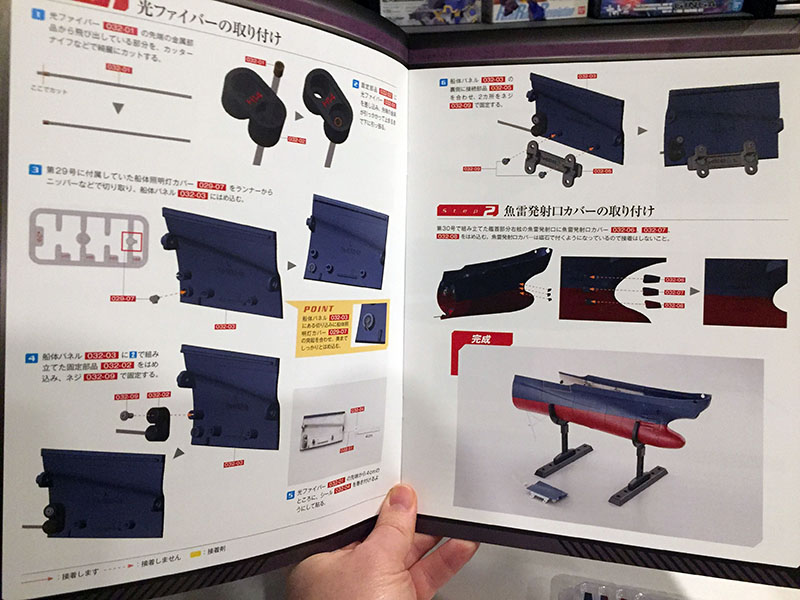
Hello, Volume 33.
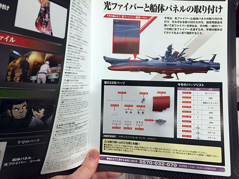
Still approaching the midship area.
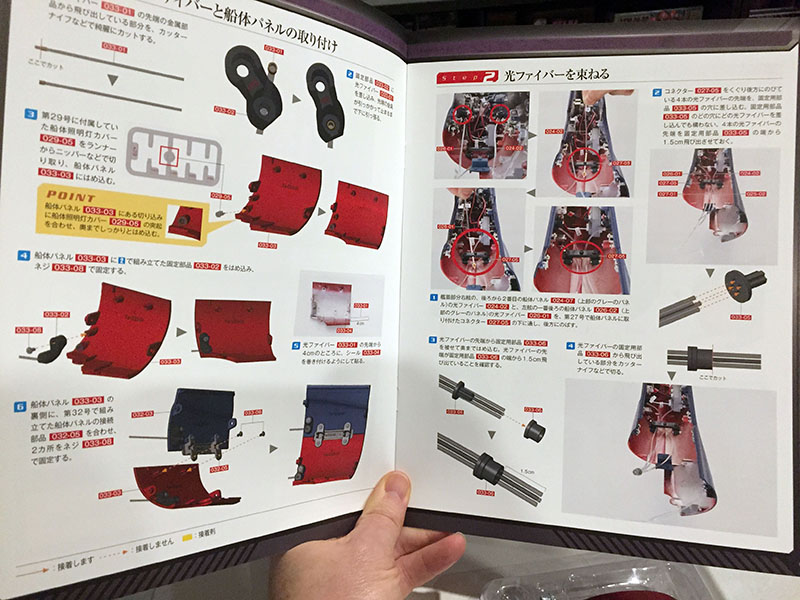
Another hull plate and some fiber capping to be done.
By the end of this, we’ll have another whole section of hull completed.
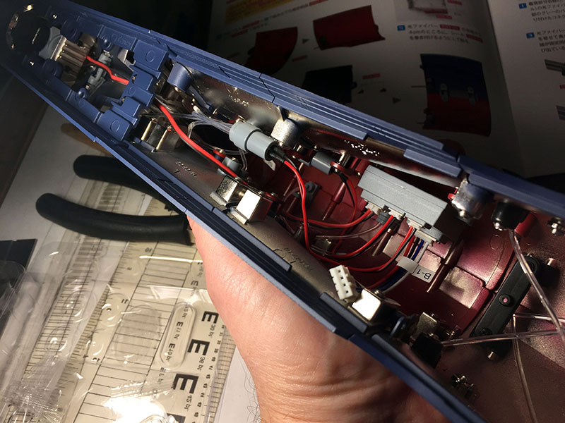
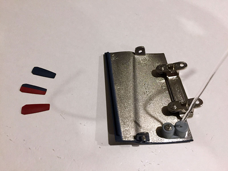
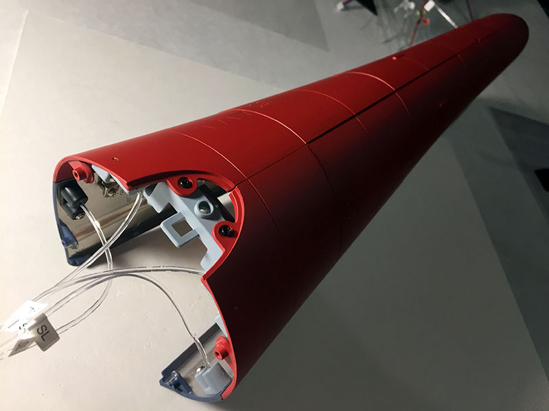
Here’s what the interior looks like so far. All of that is for running lights and the WMG. This is still just the beginning.
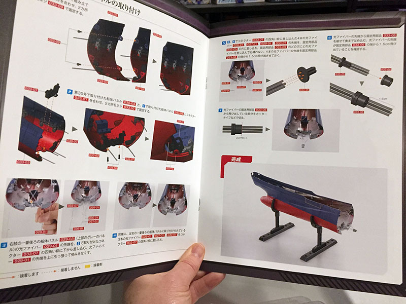
Two new hull plates bracketed and lights installed.
They’re now attached and four stray fibers have been capped. This cap will eventually be mated with a light bulb.
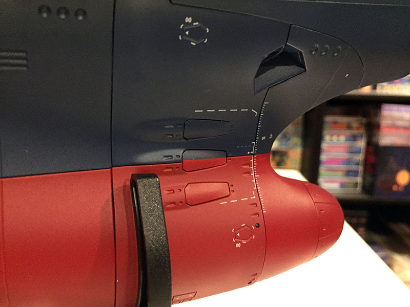
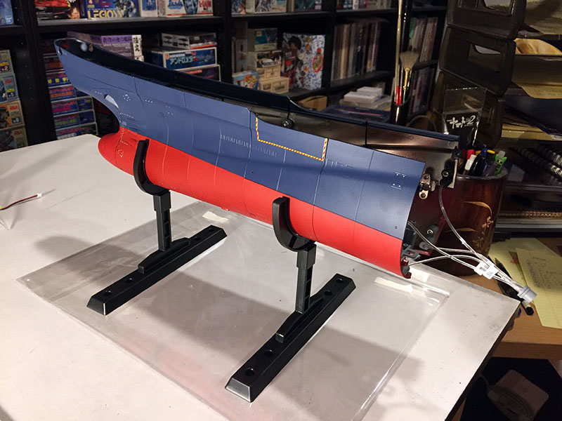
Here’s what the ship looks like underneath. That’s quite a mismatch running down the central axis, but there’s nothing to be done about it. When I first learned how large this model was going to be, I thought the only sensible way to construct it would be just like a real ship; lay down a keel and build the hull around it. They’re not going that way here, and I think this is the result. A keel structure might have gotten in the way of the internal electronics, I don’t know.
All done with Volume 33.
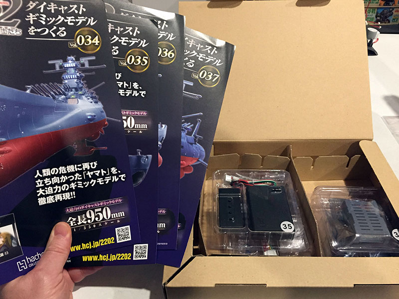
Next set of four. Some major electronics work coming up.
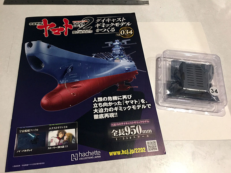
What are we doing here, Volume 34?
Something important for the upper hull area.
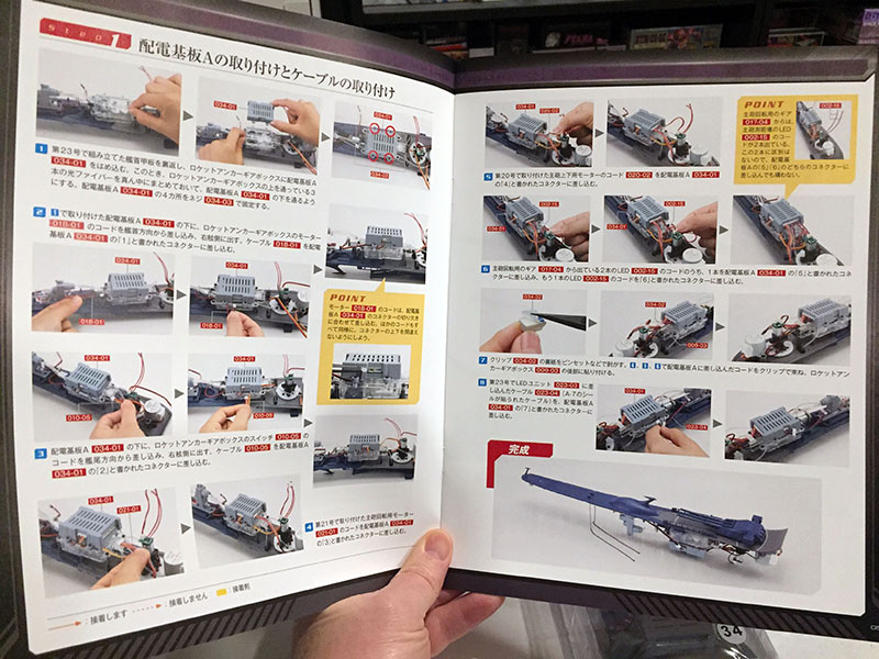
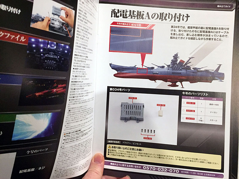
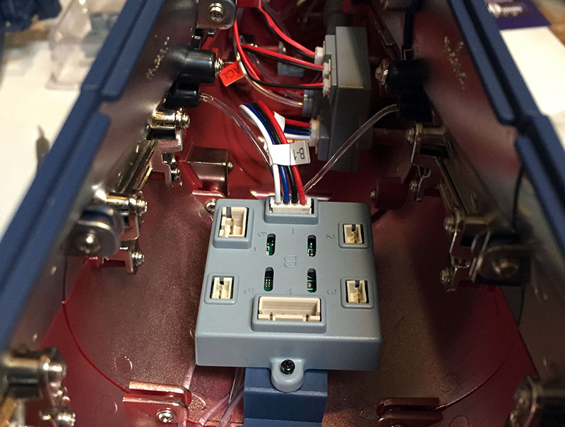
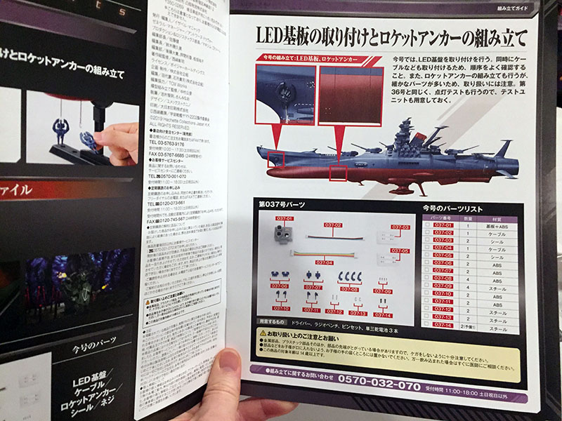
It’s a pretty serious looking junction box, and it gets bolted to the gear box for the rocket anchor chains.
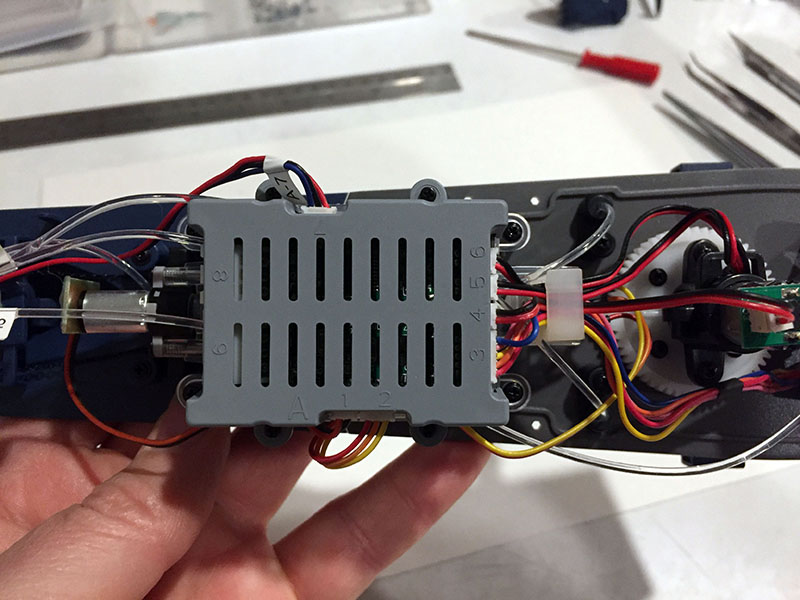
There it is. NINE different ports! And seven of them are now occupied.
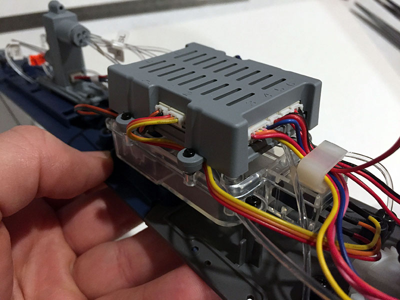
Part of the engineering meant figuring out how to tuck and secure all this stuff so you could actually fit it into the hull.
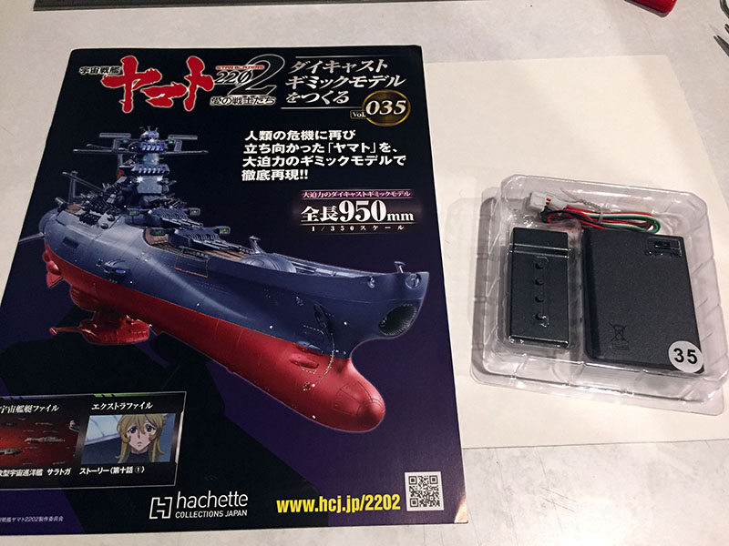
Volume 35! Exciting! I know what’s happening next…
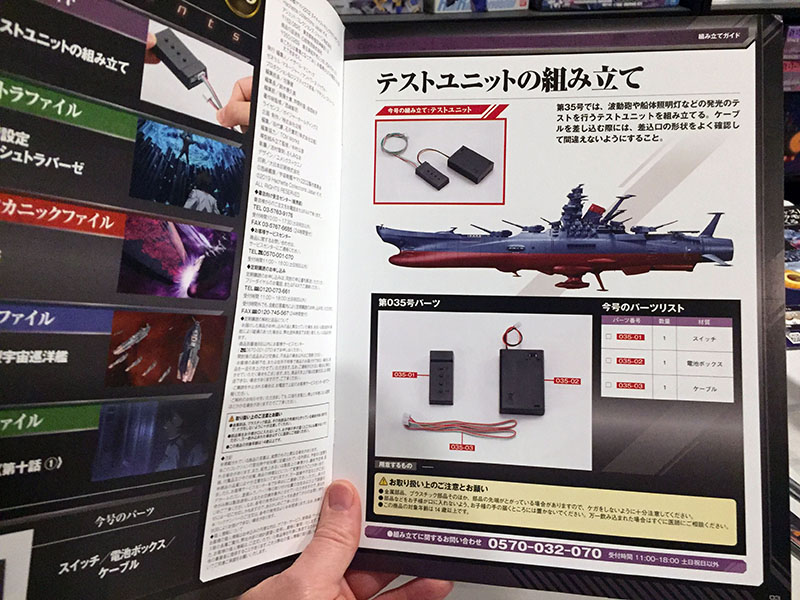
It’s a control pad with a battery box.
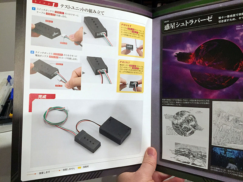
SUPER easy to assemble.
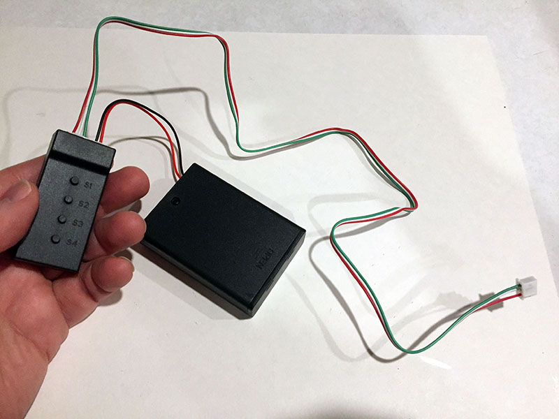
This will be used to test the electronics installed so far.
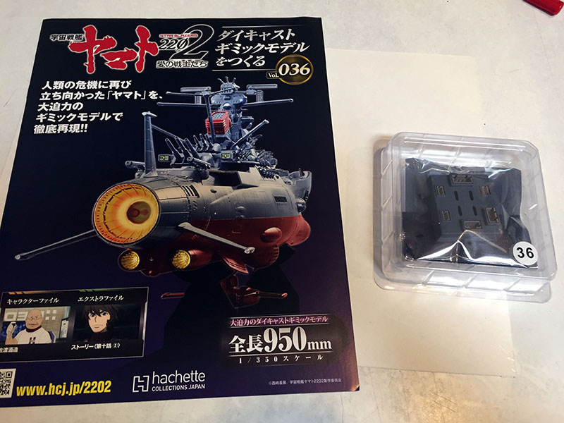
Volume 36 gives us another important-looking gizmo.
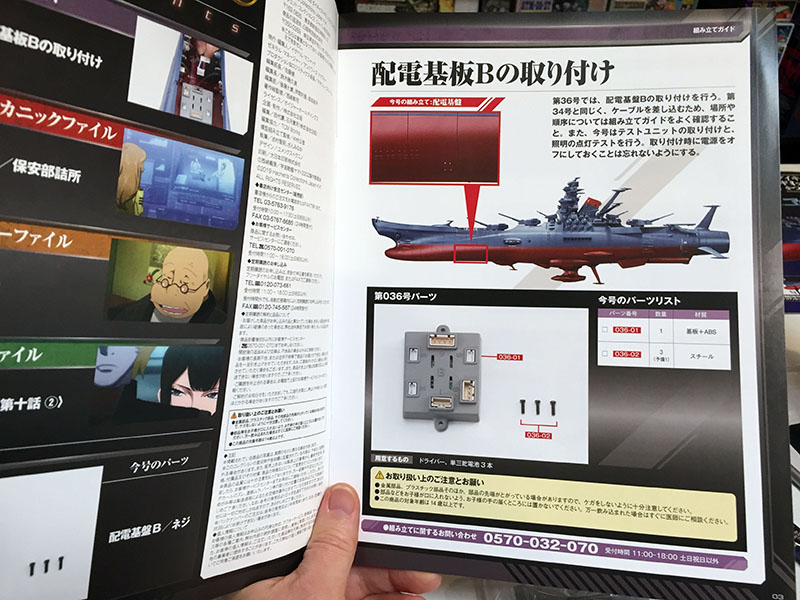
A second junction box (the last one was A, this one is B) for the lower hull. Among other things, I think it contains the programming for the WMG.
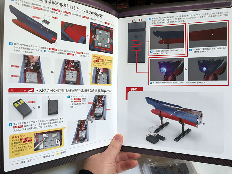
Once this is installed and plugged up, we’ll see if all this labor pays off.
Okay, the box is in place with the first plug installed. It supplies power to the previous junction box. We plug the control pad into it and…
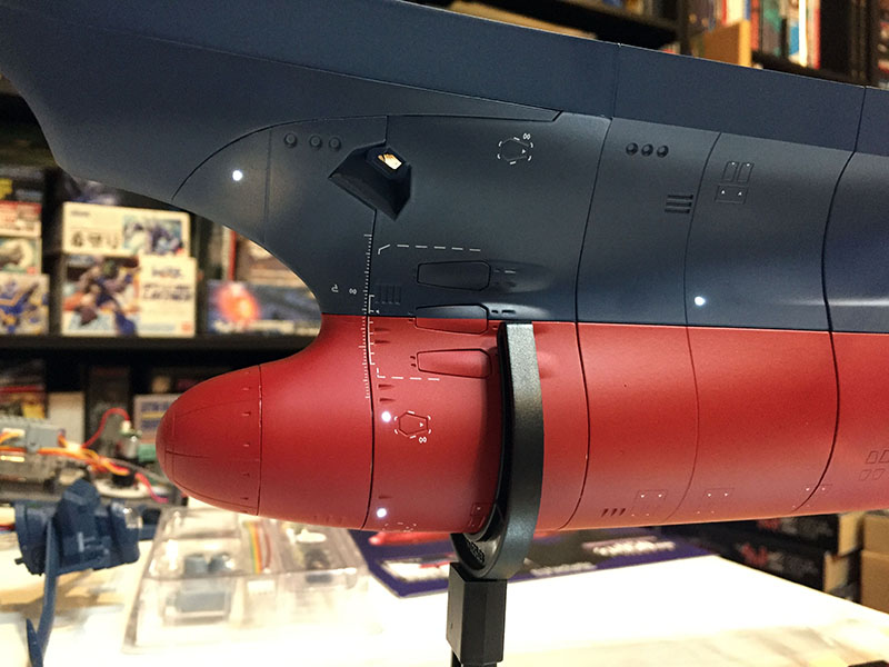
HOT DAMN! THE LIGHTS WORK!
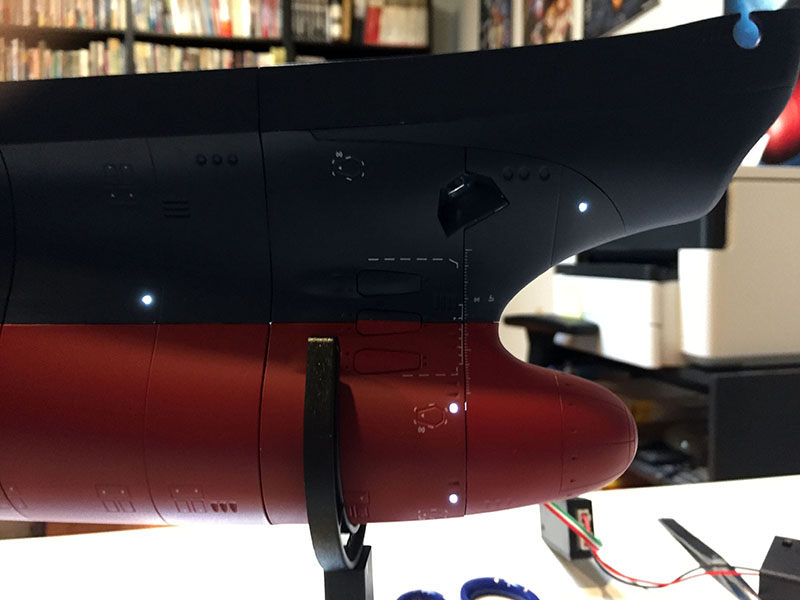
ON BOTH SIDES!
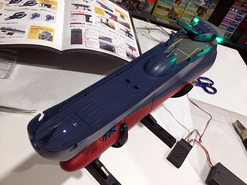
They even look pretty from above! But there’s still the BIG one to try out. You know the one I mean…
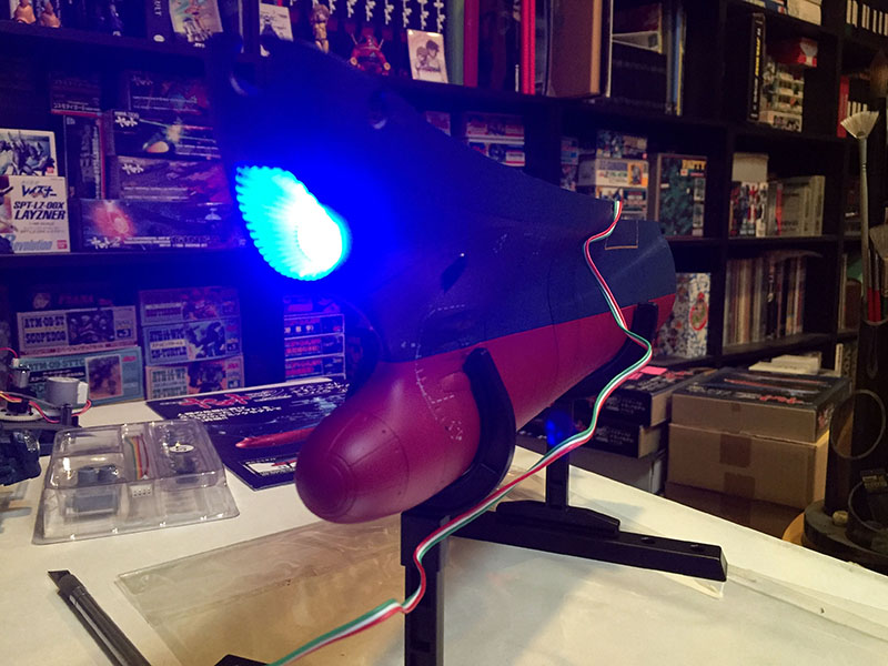
JEEBUS CRIPES, THAT’S BRIGHT! There’s also a sequence programmed into it. The light amps up, starts flashing, and then goes solid. This will sync up with a WMG sound effect that is programmed into the permanent base stand coming at the end. In the meantime, you could easily read by this light.
All right, calm down, time to get back to work. And “work” is the right term for what’s coming next.
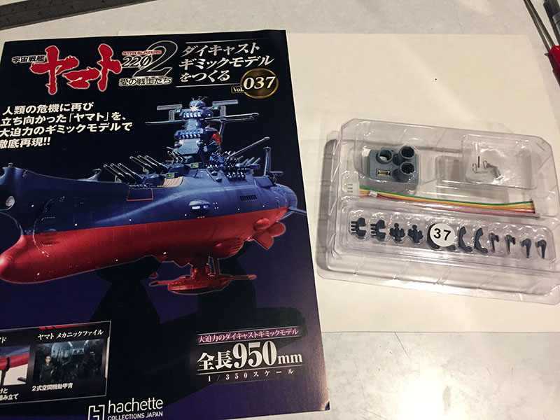
More lower hull work and some rocket anchors.
We’ll install the first LED bus and put the anchors together.
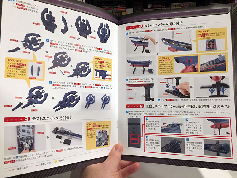
These are by far the biggest rocket anchors to accompany a Yamato model, but that doesn’t mean they’ll be easy to put together.
Oh, and another electronics test is coming up. That should be fun. As long as it works.
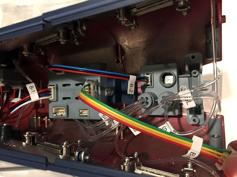
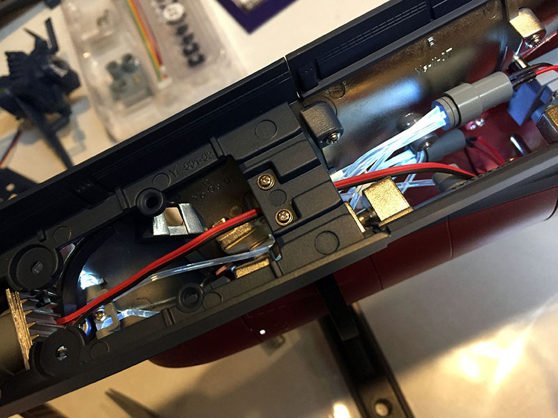
The LED bus is installed and three items have been plugged into it already. The rainbow-colored wires will eventually connect the junction box to another junction box. They will relay power to each other.
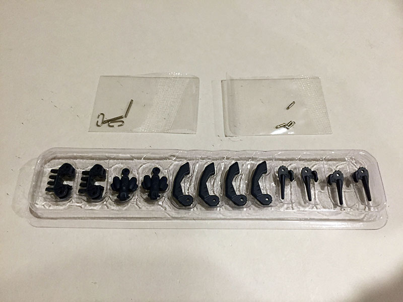
And now for the anchors. This is a ridiculous number of parts, and none of them glue together. They either snap in or will be held in with hinge pins. Very. Tiny. Hinge pins.
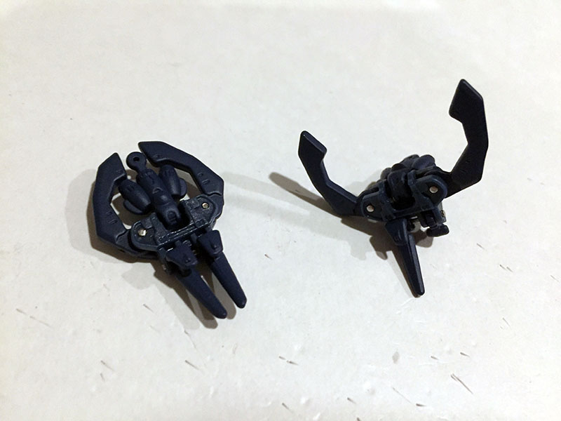
After almost an hour (and a LOT of 4-letter words) the anchors are assembled. The one on the right shows you what the hinge pins do. I’ll be honest, I didn’t enjoy ANY of this process. As soon as I saw how tiny those pins were, and the tension required to get them into place, I just KNEW one of them would pop off and fly across the room. And of course it did. It launched into the air and I heard it land somewhere.
I decided then and there, screw this. I’ll never find that pin. I’m gluing these together. I tried, but there wasn’t enough contact for glue to work. I had no choice but to go looking for the lost pin. Miraculously, I found it. And ever so slowly got these monsters assembled. Another pin attempted to escape, but didn’t clear the tabletop. Little bastard. Now you’ll never get away.
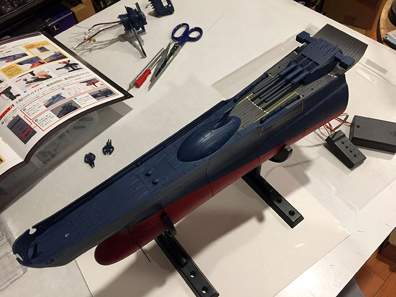
With that nightmare over, I got the pleasant task of fitting the forward deck onto the hull. Amazingly, all those guts made way for each other. No collisions anywhere!
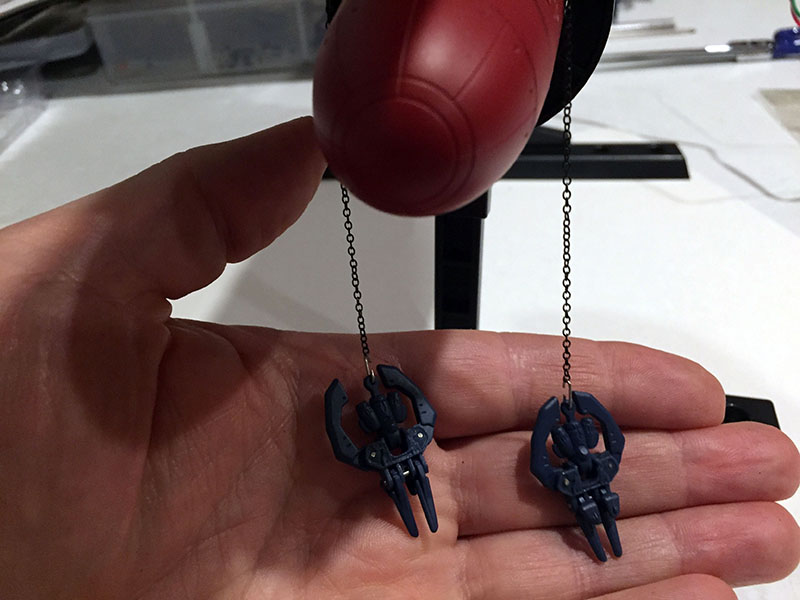
Getting the anchors on their chains was the next nightmare, though. Those little C-shaped clips were completely inadequate, constantly slipping out of place. The only way to keep them under control was to get out the pliers and crimp them together, like a jeweler closing loops on a necklace.
I realized after the fact that if I need to lift the forward deck off again, the anchors can’t be removed without opening (and probably ruining) the clips. Sure enough, that very maneuver was called for in a subsequent volume. Oh well.
And then…ELECTRONICS SUCCESSFUL! All the lights come on, the anchor chains raise and lower, the first gun turret rotates, and the individual cannons go up and down just like they’re supposed to. Oh, happy day!
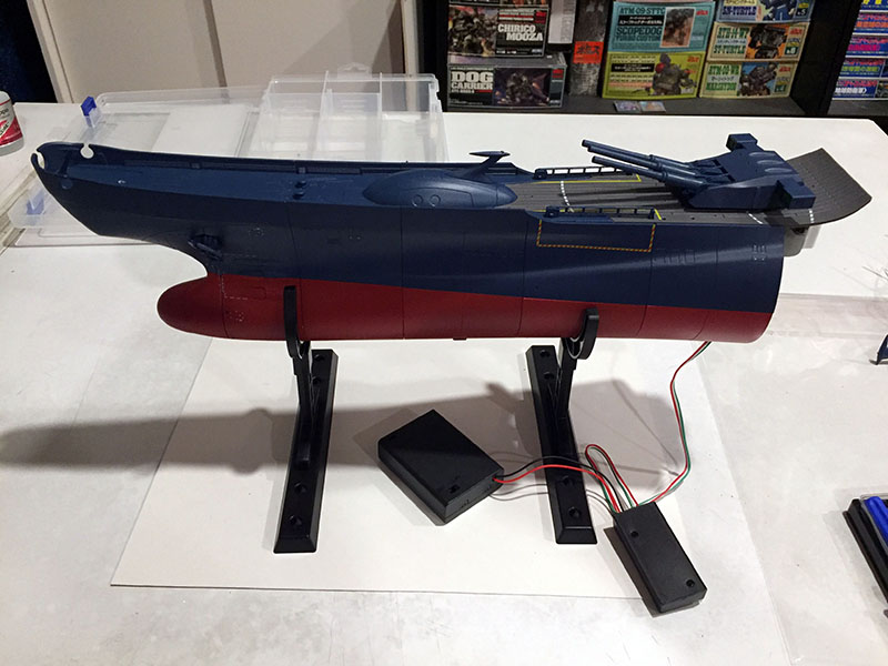
What a lovely sight.
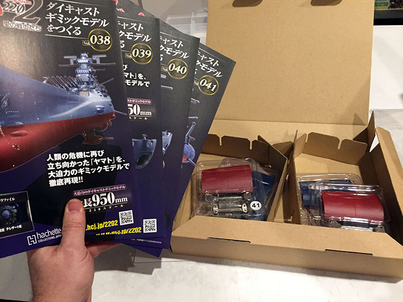
Next four volumes. Looks like some nice, easy hull plates to balance out that anchor business.
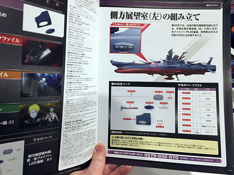
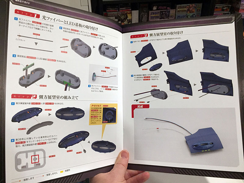
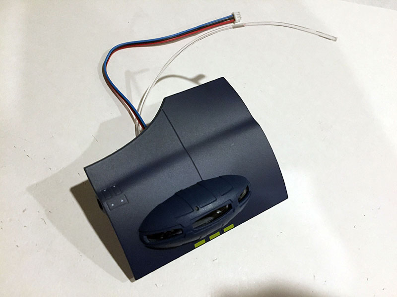
First sign of the lateral observation decks.
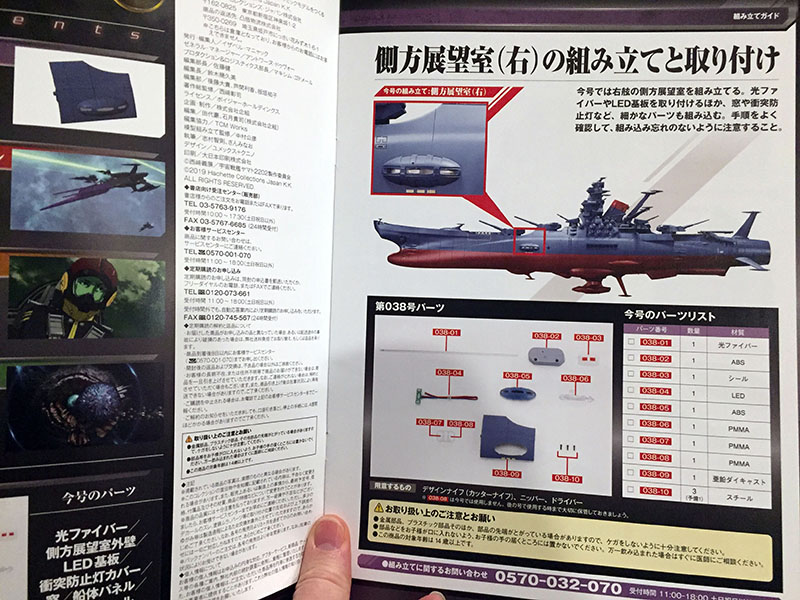
Yep, here we go. Fewer parts = easier sessions.
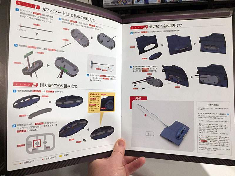
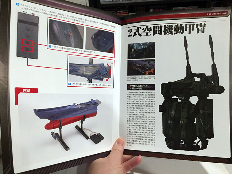
Just two pages. I like the looks of this one. Note: at lower right we find that correction for the fiber bundling back in Volume 31. Hachette was really, really sorry about that. “We deeply apologize for the inconvenience caused to our readers.”
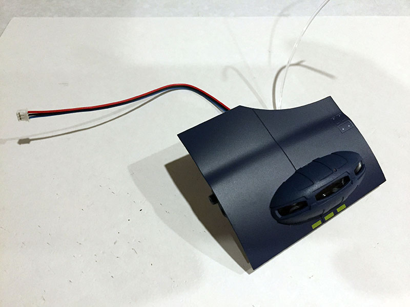
Volume 38 done in just a few minutes. The only problem here was that the screws they provided to attach the bubble were too long and made it jiggly. But I still have all the extra screws from previous volumes, and I found a shorter one that took care of it.
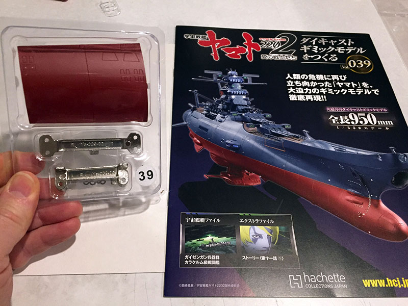
Volume 39; next hull plate.
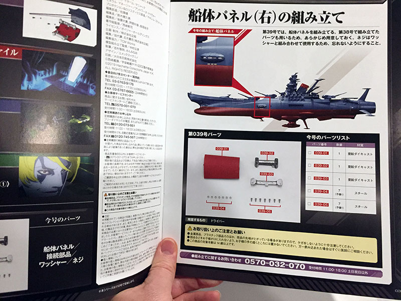
Same section of the ship, starboard side.
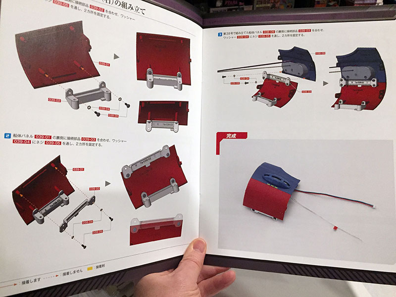
This should go well.
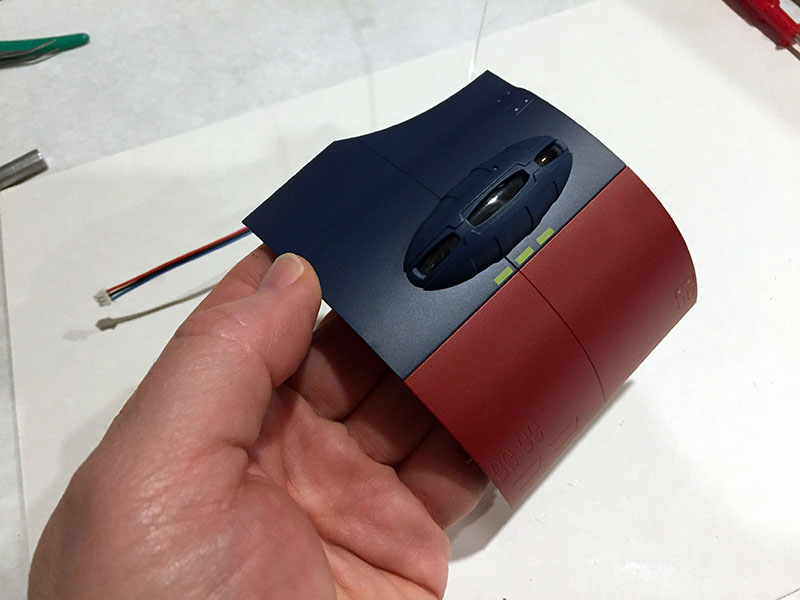
Right on.
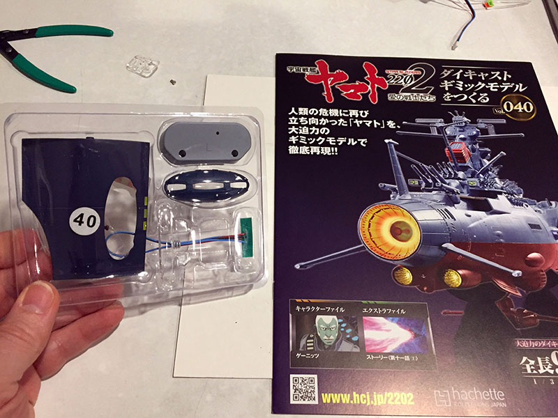
Volume 40…
Same as Volume 38, but now on the port side.
Yep. No problemo.
Done. Same jiggly problem, same fix.