
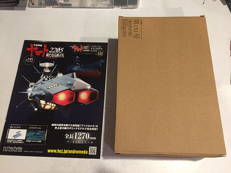
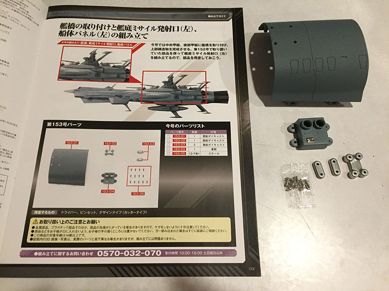
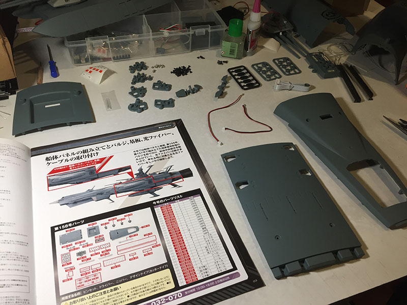
With that horrible bridge tower behind us, it’s time for Volume 41.
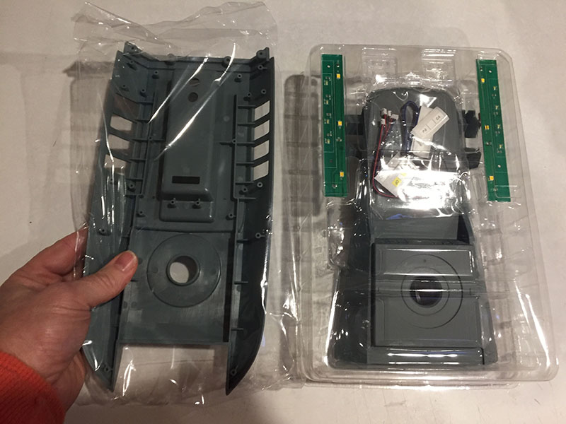
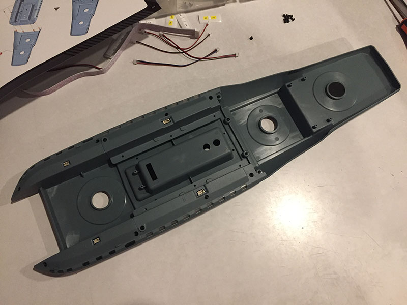
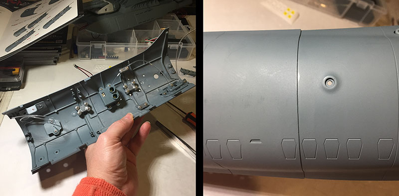
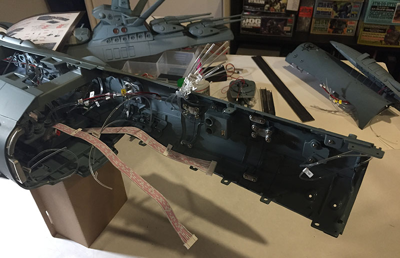
The box contains two of the biggest single pieces, forming the bed the tower will sit on.
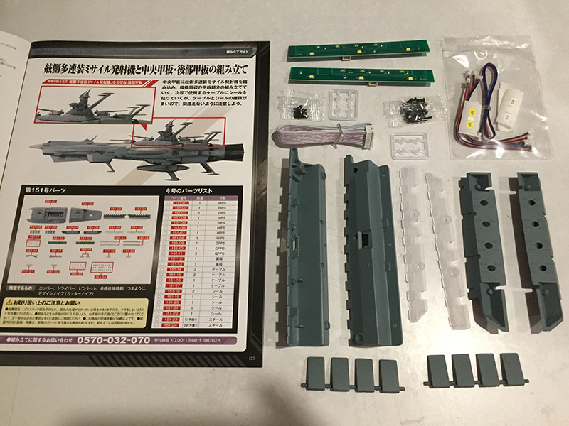
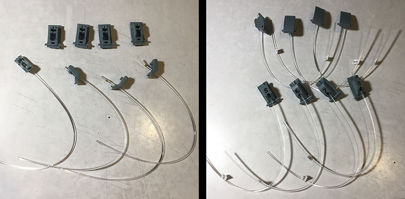
Most of the other parts have to do with lighting for the bed.
Laid end to end, these two pieces are over 18″ long.
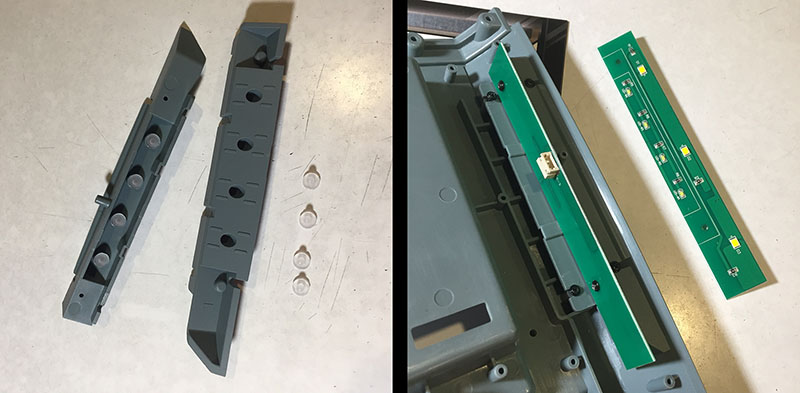
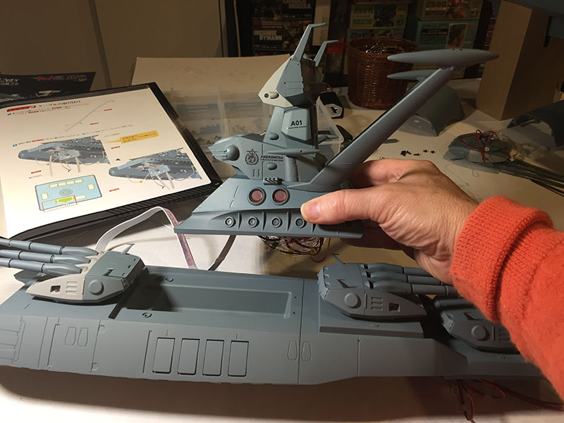
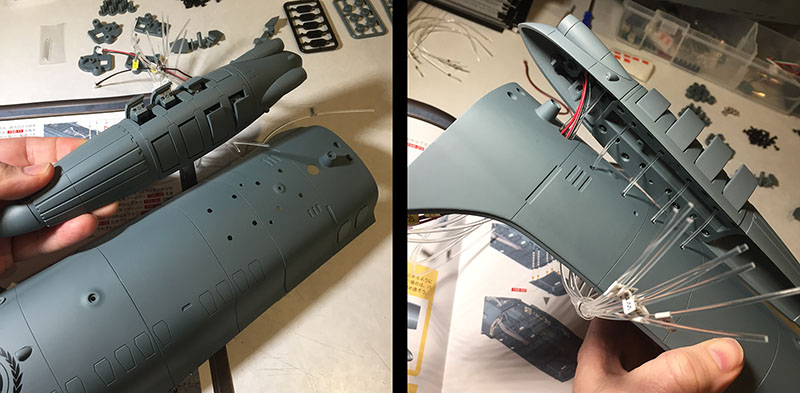
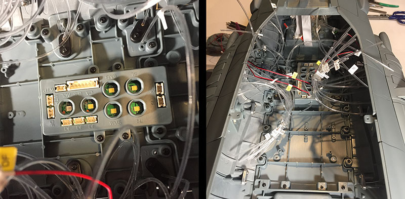
Construction begins with the front half. These planks and LED boards are positioned at the flanks.
They both hold in and light up a set of hatches that flip open. On the Yamato kit, they would also have been motorized in some way. That’s why Yamato was 110 volumes and Andromeda is only 60.
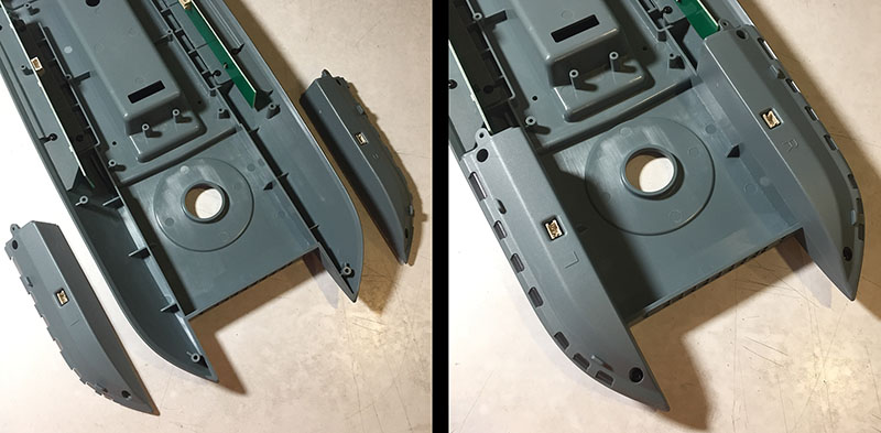
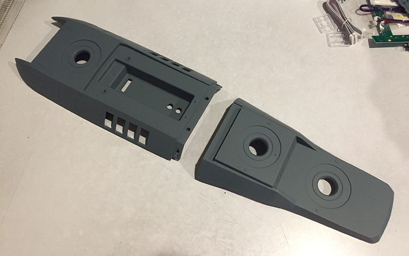
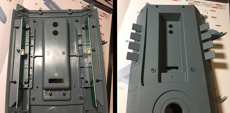
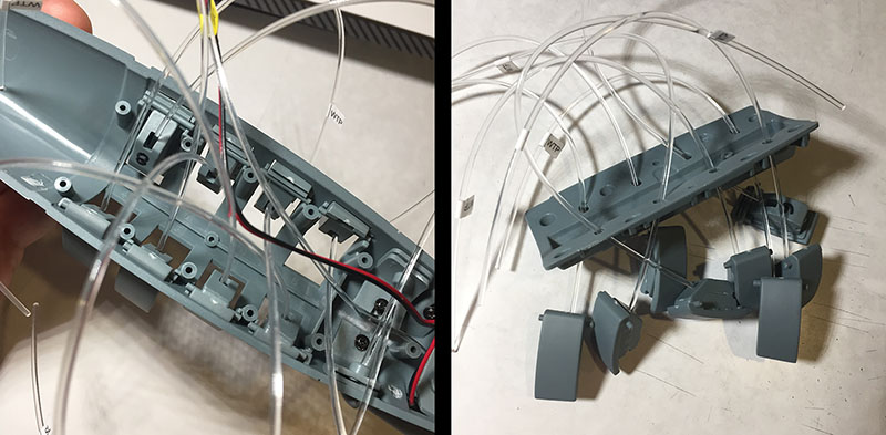
These modules left over from Volume 40 find a home in the front end of the bed.
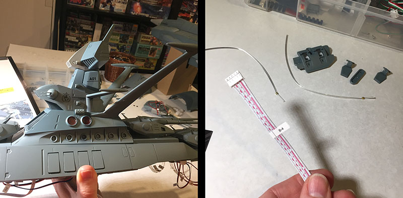
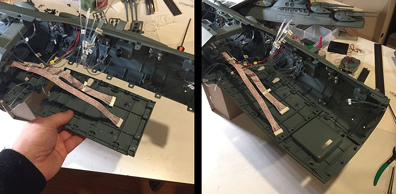
Left: So far it resembles a sled more than a bed. Right: These bits will continue the row of lights we just started.
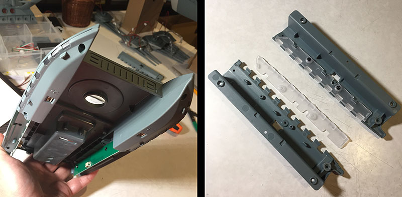
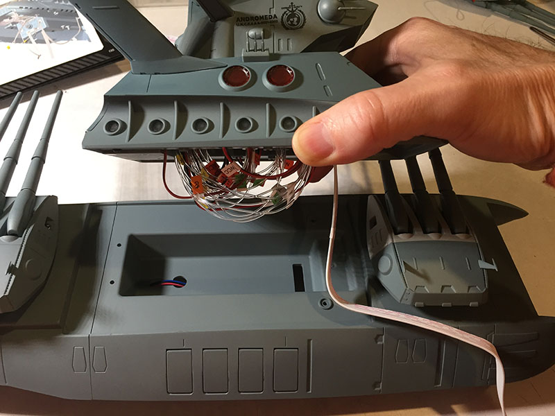
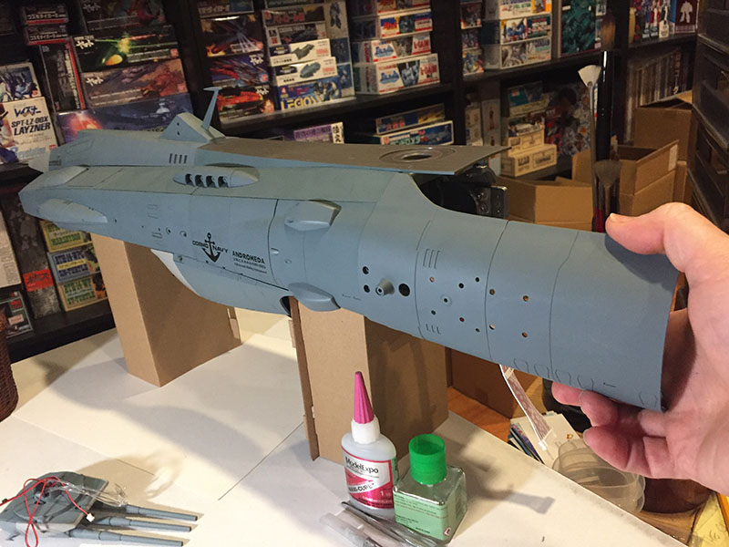
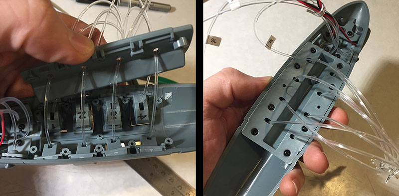
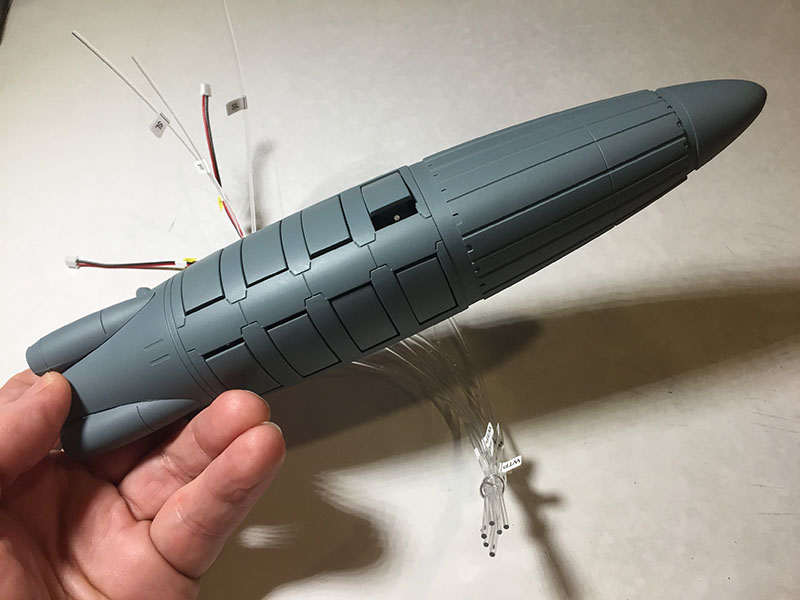
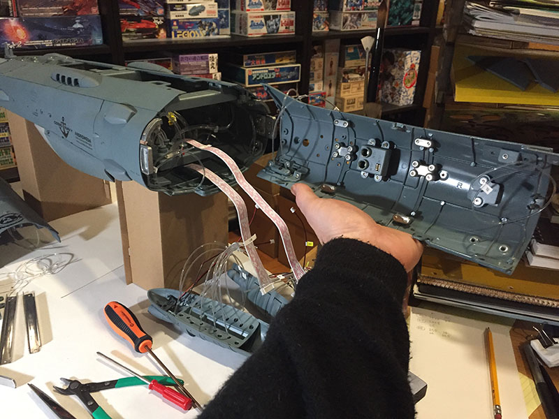
And all together now.
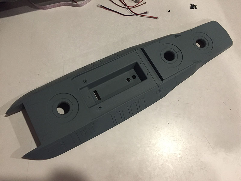
That is one honkin’ big piece of ship.
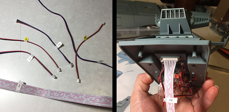
We wrap this one up by labeling some wires and installing a HUGE ribbon cable into the bottom of the tower. This is where the lighting juice will come from.
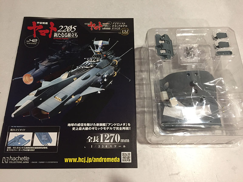
Next up, Volume 42.
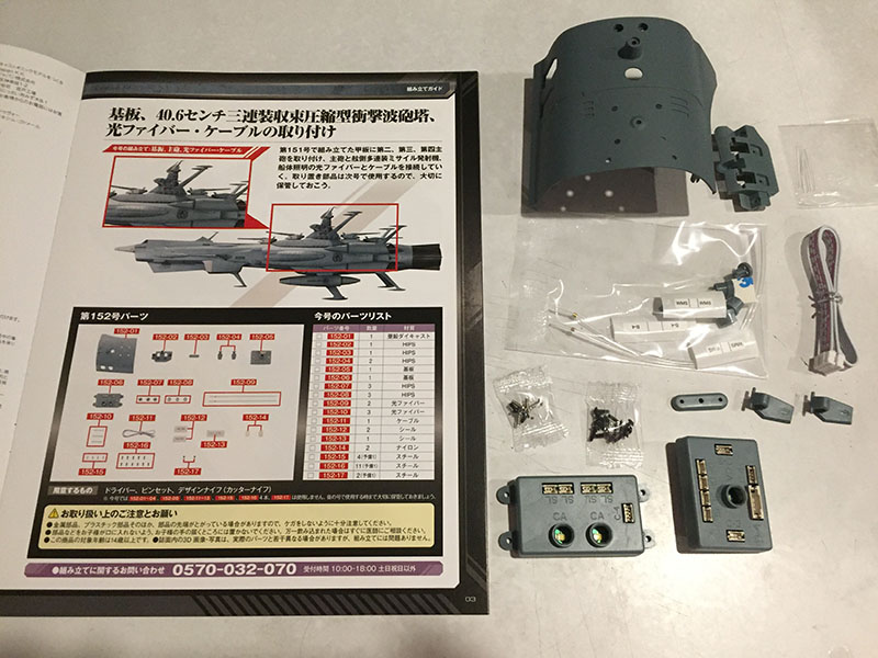
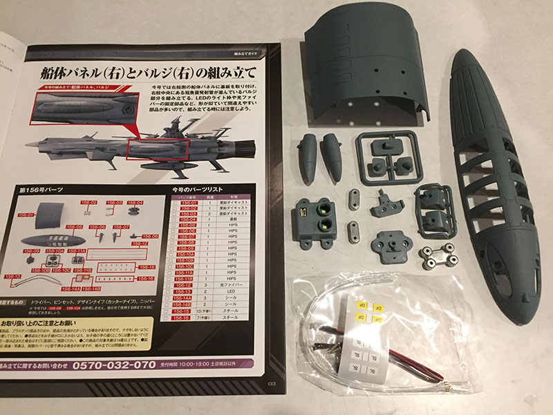
This one has the first side hull segment we’ve seen in quite a while. The last one was all the way back in Volume 27. There are also two distributor boxes and fiber caps. We’re gonna be doing some plugging.
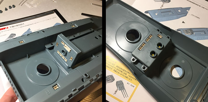
One box goes in the front of the bed, the other in the back. The cannons and flank lights will plug into these.
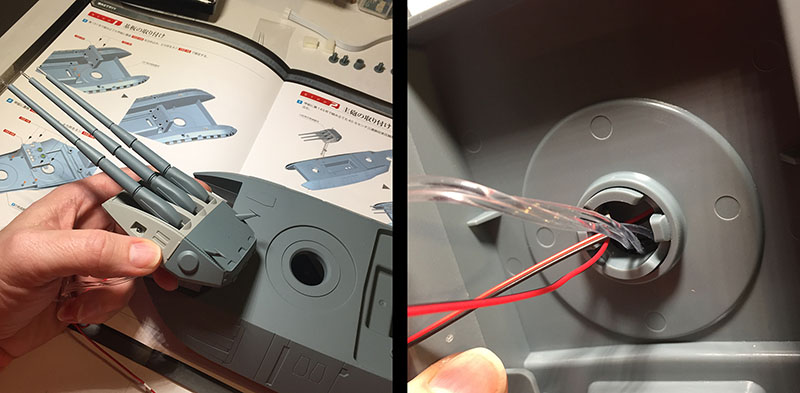
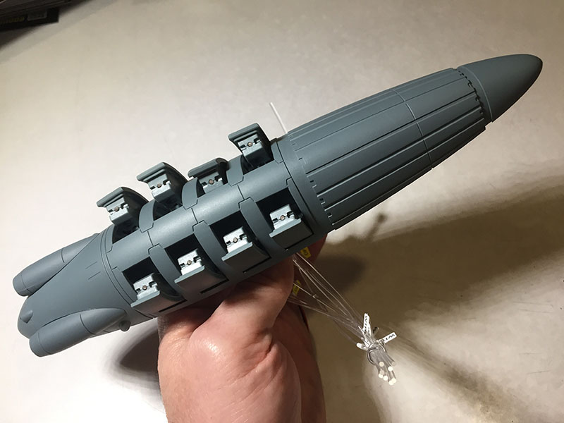
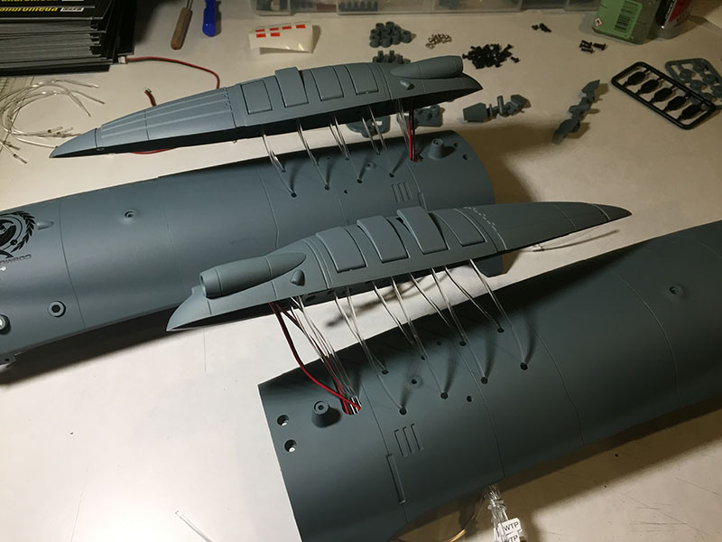
Main turret #1 will go into the forward section of the ship at a later time. We’re starting with main turret #2. It fits into its socket with a satisfying SNAP. Yamato‘s guns were all motorized, so it was a much more complex installation.
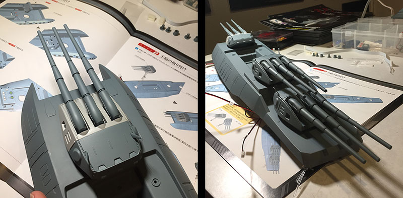
Left: main turret #2 is standing proud. 3 and 4 go on just as easily in the back half. And now you can see the inequity of the engineering in the individual barrels. They all have different levels of tension, as dictated by those lousy rotten fibers threaded through them. Turret #4’s middle barrel has no tension at all. Nothing to align it with the others. I’ll have to glue in something to give it lift. Very disappointing. Doesn’t seem like this was thought out at all.
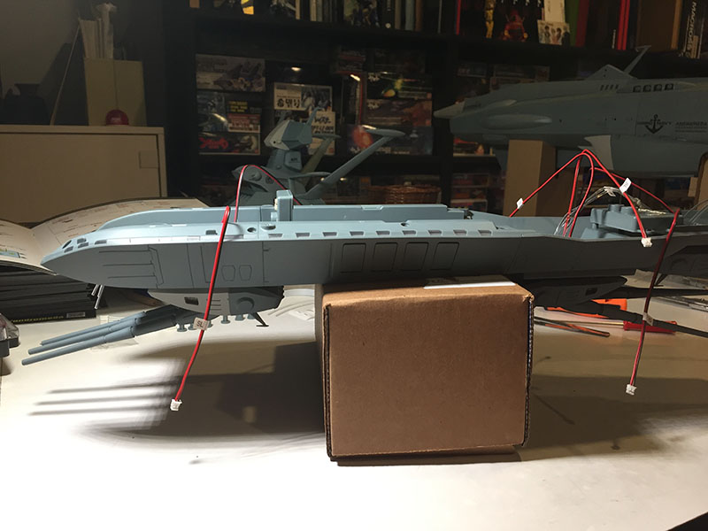
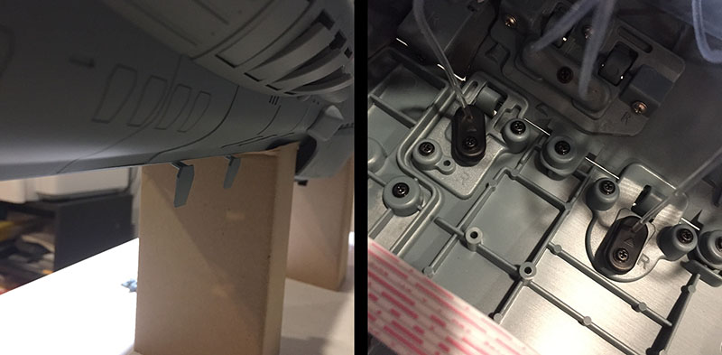
Speaking of which, the wire handling has to be done by flipping the whole bed over. If I were to lay it on the table, the only things supporting it would be the tiny fins sticking up from the turrets. They’re just glued in, and would absolutely break if I didn’t have a box to put the thing on. Again, couldn’t they see this coming and provide a safety measure? Or better yet, deliver the tiny fins until we’re past this part of the operation? Sigh.

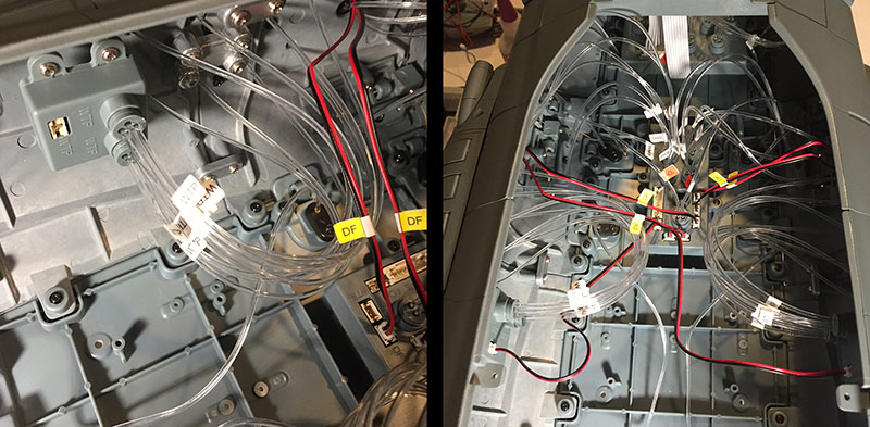
We’ll begin the fiber and wire operation on the back half.
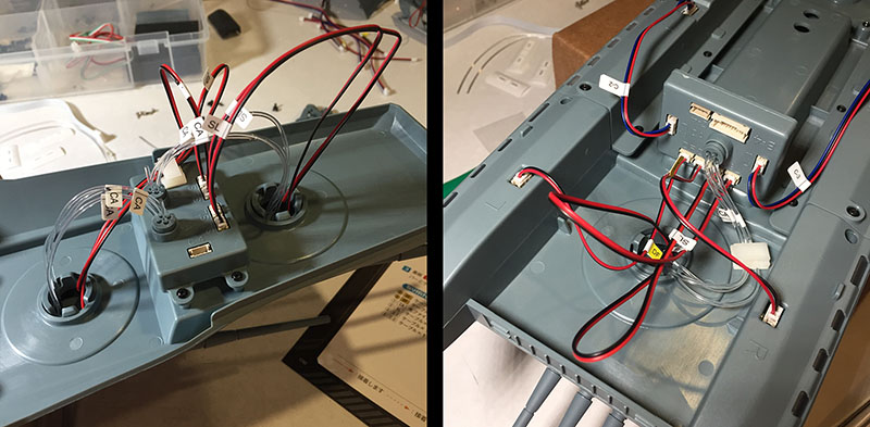
Left: everything plugs into the box without a fuss, but the fiber caps are pretty loose again. It’s a little worrying that they’ll be suspended upside-down.
Right: with that done, we take care of the front half. Again, no complaints. Everything seems easy after that tower.
The last step is to connect the two boxes with a ribbon wire that will send power from one to the other. It slips through a couple holes in the bed, and Bob’s your Neighbor.
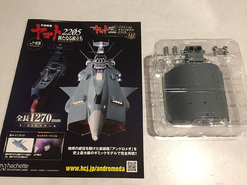
Volume 43 gives us another side hull segment.
After all the fussing and sweating and fighting with micro parts, it’s SO nice to have a hunk of metal to work with again. Nearly everything over the last 20 volumes has been all plastic.
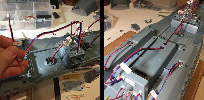
We start this one with a BIG MOVE: securing the tower to the bed. There’s a large trough right under it to accomodate all the noodles.
It seems big enough until you actually try to stuff them all in, then you find that you have to push a few back up into the tower and count on the screws to subdue the rest. It’s a fighter.
Left: there you go, tower. No more surprises from you, all right? Right: next we have another ribbon wire to plug in.
Left: it goes into the distributor box at the front of the bed. With that, the entire superstructure is DONE. VICTORY LAP.
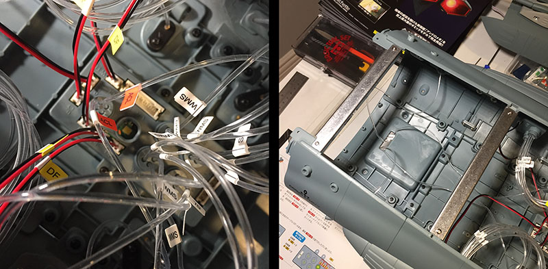
Right: now, our blissful return to unchallenging hull segments. This one (from Vol. 42) will have a pair of hatches on it.
There’s an apparatus to hold them on from the inside, then two fibers poke through.
Left: the ends get trimmed off, then we get a preview of what this will look like.
Right: next, a small distributor box gets attached to the inside of our new hull segment. Fibers will plug in here.
Finally, both of these segments get bolted together. The attach points are heavy duty, like someone expected these segments not to line up on their own. And they are just slightly off. Hope it’s not too much.
Just for overall reference, here’s where the new segments will join up with the previous ones.
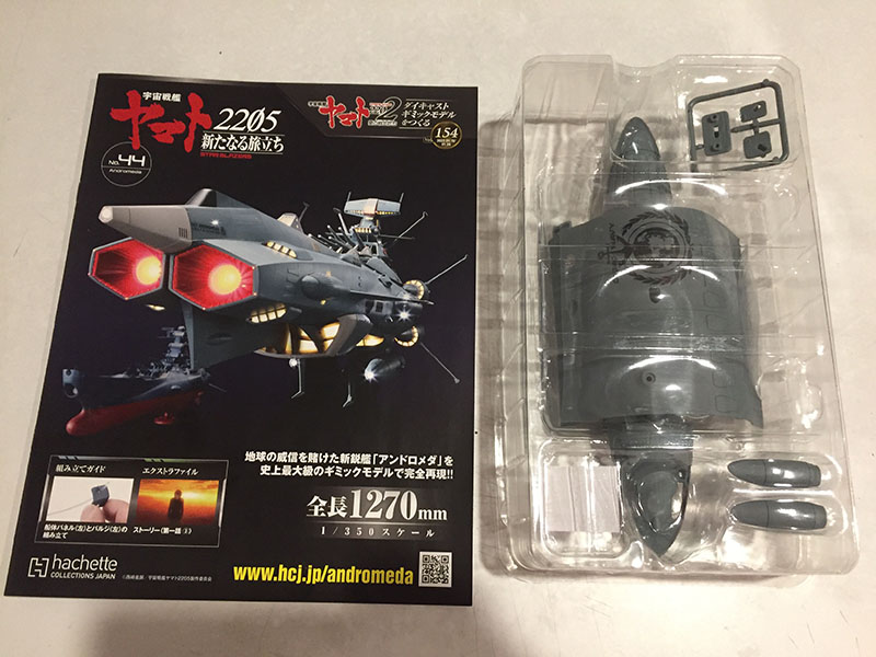
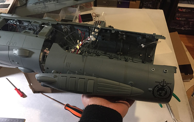
Moving on to Volume 44.
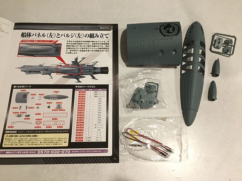
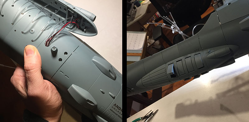
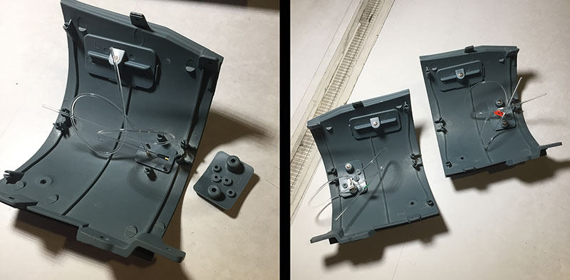
It gives us another new segment and the main body of the “bulge part” that will attach to the side of the ship.
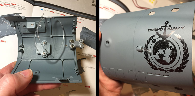
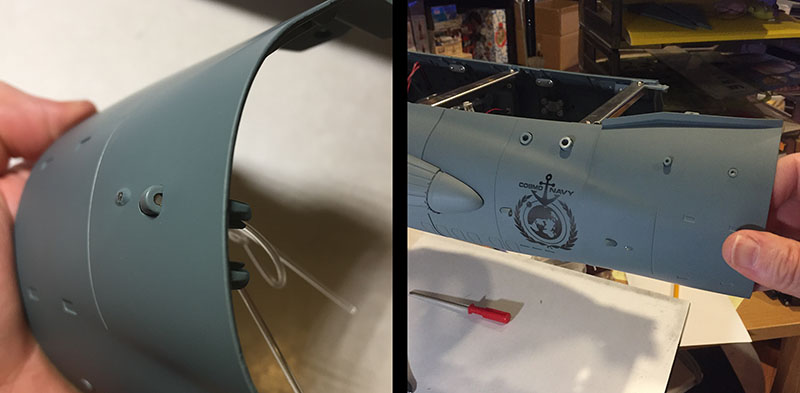
The inside of this segment gets a couple attachments, including one fiber. As you can see on the outside, the fiber is positioned to light up the Cosmo Navy emblem.
Next, we attach it to the previous two segments. The misalignment is more severe this time. Again, hope it’s not too much.
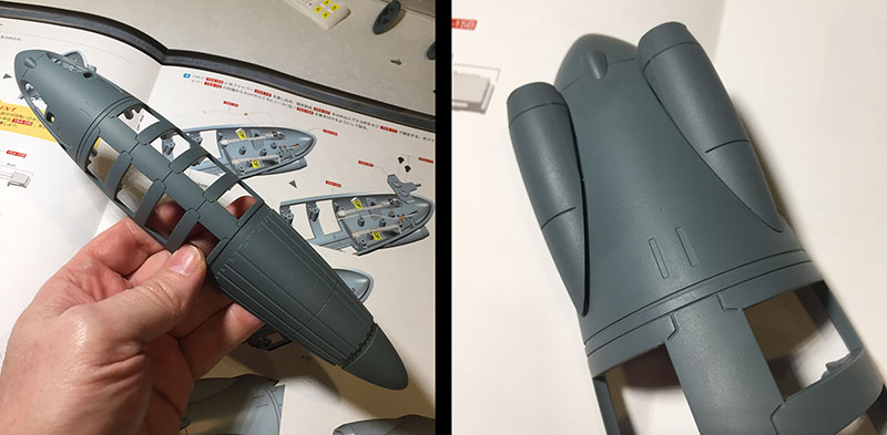
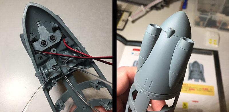
Now we turn our attention to the “bulge part.” My first impression is that it’s kinda lightweight. Step one is to attach two thrusters (or whatever) and there’s a problem with the one on the left. It’s held on by a screw, but it’s not seating properly.
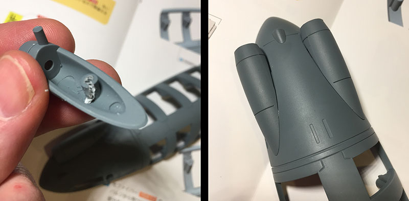
I take it off to see why, and there’s the issue. The screw tore right through the plastic socket. No choice but to superglue it now. Don’t get me started…
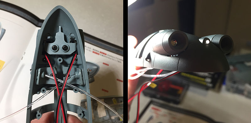
Wires and fibers get installed, and we get a lighting preview. The thrusters contain light bulbs instead of fibers, so they’ll be quite a bit brighter.
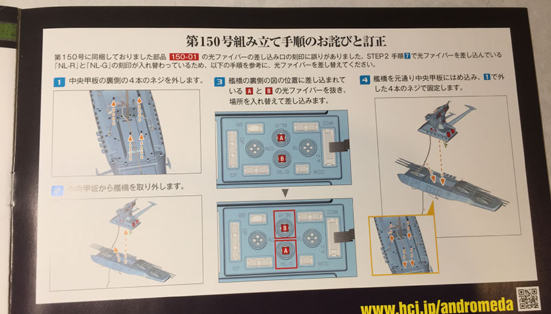
Here’s a nice laugh to finish this volume on. The instructions contain a “whoopsie” message about the lighting scheme in Volume 40 (underneath the tower). It seems some chucklehead switched codes and two fiber plugs need to be swapped with each other. So now you need to remove the tower from the bed, make the switch, and screw the tower back on. HILARIOUS!
It would be much less funny if I hadn’t done my research ahead of time and made this switch already.
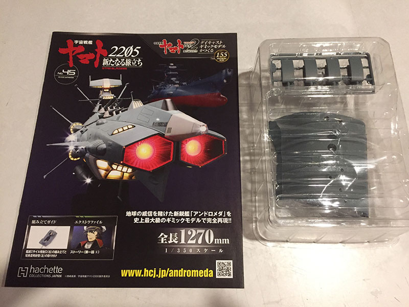
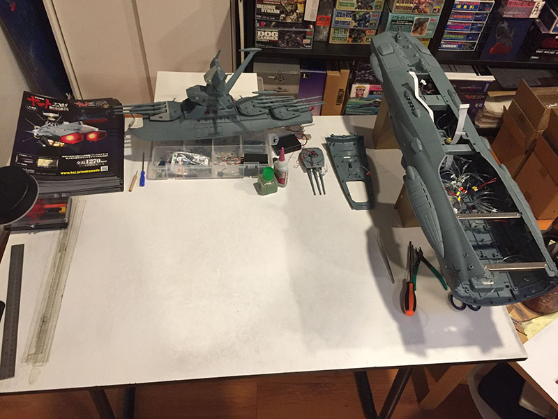
Here we are at Volume 45. Just 15 more to the end!
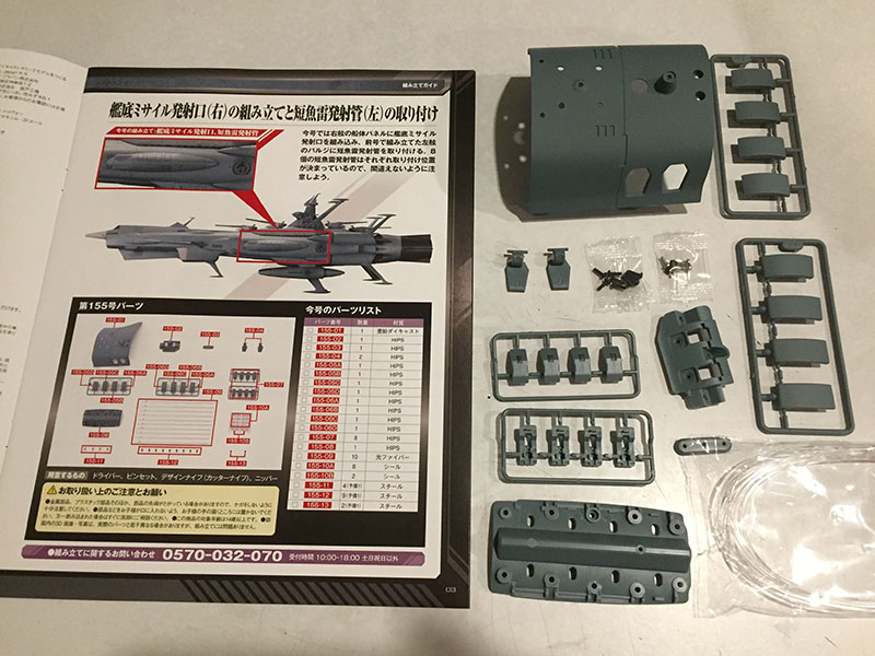
We jump over to the other side of the ship with a new hull segment, and get a bunch of parts for the “bulge.” It has a surprising amount going on.
The hull segment comes first. It’s the mirror of the one from Volume 43, so we’ve already been through it.
Now for the “bulge” parts. There are two sets of modules, each with a fiber in them, for a total of 8. The parts are numbered, but as soon as you glue them together (yechhh) the numbers get covered up, so it’s wise to number them yourself since they’re not all exactly the same shape. AND the instructions call them out with the numbers 1-8. This was another very valuable note I picked up from a Japanese builder’s blog.
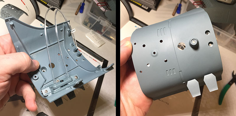
Next we place all eight of these modules into the framework and OH MY GOD those fibers are a nightmare. They all have to be threaded through a plate that will hold the modules down, and the second you start threading the modules LEAP out of their resting places. The instructions just hand-wave this away, like fiber tension doesn’t exist.
After a few unsuccessful tries (and a lot of swearing) I decide to go the other way, threading them into the plate first.
Left: with the plate and a twist-tie sort of keeping the fibers under control, it’s slightly easier to get the modules into their sockets.
Right: then I bolt that plate down as quickly as I can before they can leap out again. This was much more challenging than it looks, like a 4D puzzle in the midst of a bunch of 3D puzzles.
There they are, all secured. They’re meant to flip open and light up. Again, a feature like this on the Yamato model would have been motorized in some way and they’d all have equal tension.
But here, as you can see, the tension is NOT equal. The fibers are still pulling at different strengths, so one module won’t close all the way. I hope this takes care of itself when the fibers get plugged later.
This is a good place to mention that 90% of the problems I’ve run into with this build have all stemmed from the lighting needs, specifically these endless, infuriating fiber optics. If not for them, it would be a breeze. But the whole point of this model is the lighting, so this is the deal I made. Or, as they say in Japan, this is the ship I boarded.

Here we go with Volume 46.
The pieces are already familiar. This is the flipside of Volume 44.
Simple start; attach a mini distributor box to the hull segment and bolt it onto the previous hull segment. We’re building up the right (starboard) side of the hull under the tower bed.
Then step two is to install lights in the “bulge” part. It’s repetitive when you have to do the same thing for both sides of a symmetrical model, but it sure goes smoother after you know how to avoid problems.
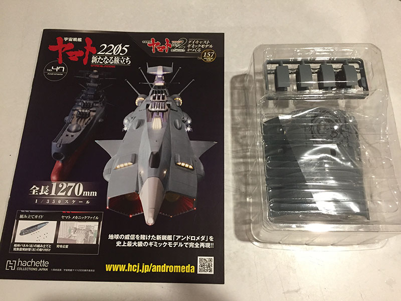
Volume 47 is the flipside of Volume 45.
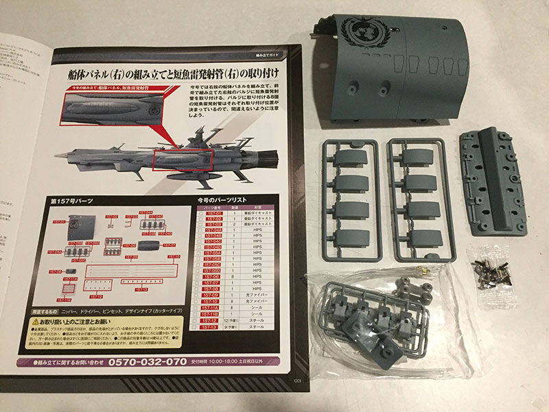
Another hull segment and parts for the “bulge.”
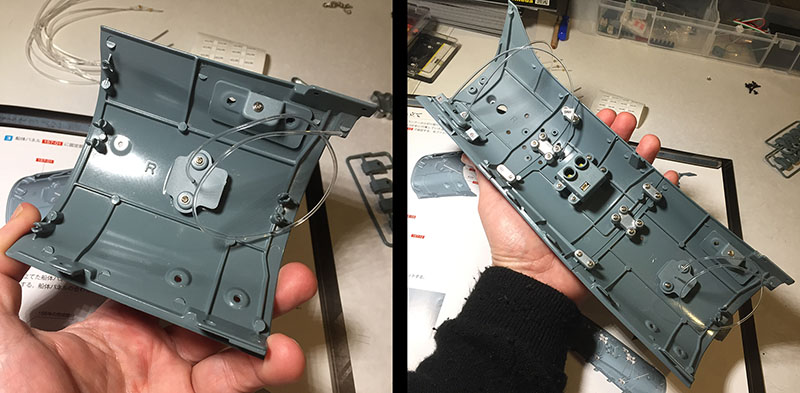
The hull segment gets a single light, then we add it to the growing chain.
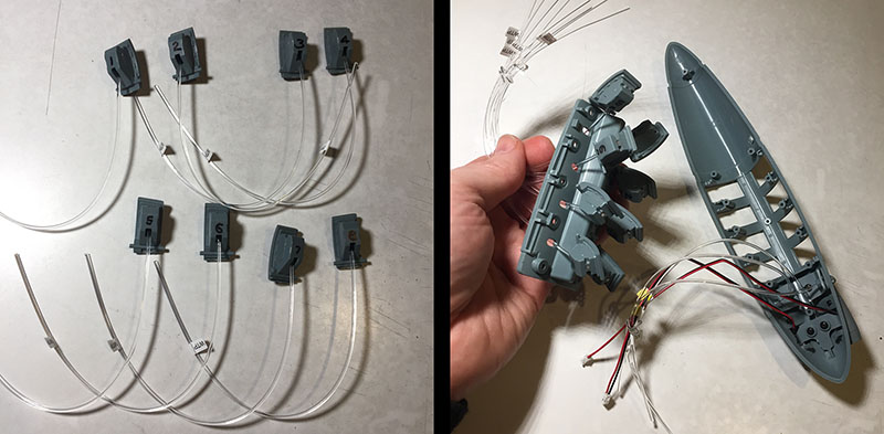
Next, we repeat the subassembly of the eight modules and prepare to install them in the bulge.
Thanks to the previous trial and error, they go in with less of a battle this time. Sometimes I think that if I could start all over with this model it would go WAY smoother. But that would also be nuts.
Right: the fiber tension is even worse on this side. Some of these models will not stay closed. Again, I just have to hope this is a temporary factor.
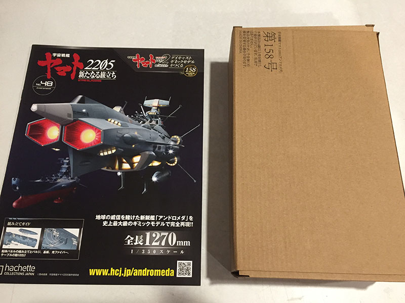
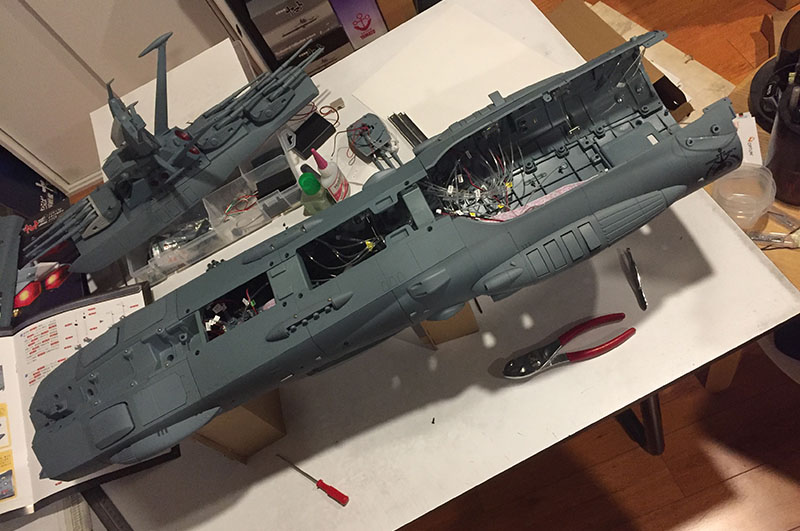
Volume 48 is one of those that demonstrates how dense the packs are becoming as we close in on the last dozen.
It’s got two large hull segments, both for the belly of the ship.
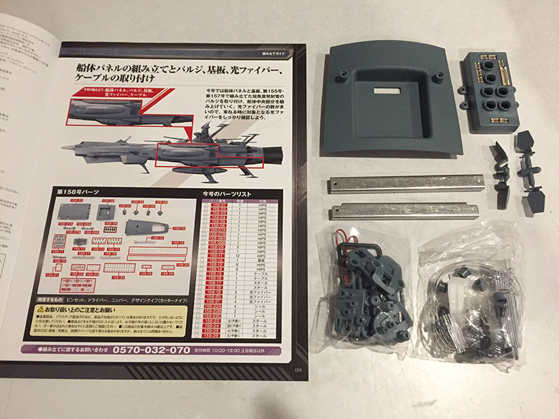
There’s also a third and a WHOLE BUNCH of internal parts that add up to a full course meal.
Big pieces indicate we’re about to make some big moves in the assembly. So let’s get started.
The first move is to attach the three starboard hull segments that we’ve bolted together. This will be the first extension to the ship body since we jumped up to the tower and made our way down to the bed. The instructions say to stick the thing on, then attach the “bulge” segment.
However, I don’t like the idea of having to wrestle all those bulge fibers through the holes in that position. Unfortunately, we can’t just attach the bulge permanantly and then stick the whole piece to the ship, because the front end of the bulge covers up the key attach points.
In other words, someone at Hachette decided not to make it easy. My compromise is to thread all the fibers and then stop short of attaching the bulge. At least the threading part would be easy.
Both sides done. Ready to attach.
Left: those two screw holes in the center are the main attach points. These are the holes that will be covered by the front end of the bulge part.
Right: attachment complete, bulge secured in its final position. Module still misbehaving.
With this piece attached, the model has reached a length of 31.5″ which is just 6″ shy of Yamato‘s full length. And there’s still an entire stern section coming.
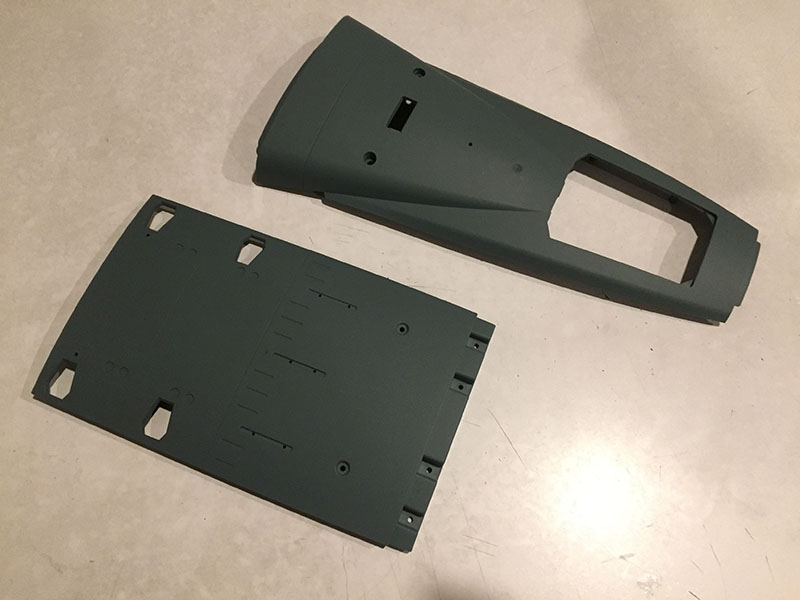
Now we attach the two belly panels that just arrived. Both are plastic whereas the side hull is metal. Probably to keep the weight down. That rectangular opening toward the back end is where the wires and fibers from the undercarriage will come in.
Next, we install two hatches to the lower hull that will flip open to reveal lights. At right you see the internal assemblies that secure the lights and the hatches.
Okay, starboard side is on, now we do the same with the port. While I was attaching the starboard side I knew this one was going to be a LOT harder. Why? A lot less space to drive the screws in. For the starboard side, I was working in open air. Now I’m constrained by the starboard hull.
It’s physically harder because I have to downshift to my shorter screwdriver, which drastically reduces the torque I can deliver. In other words, I have to grip it much tighter and turn it much harder to get those screws in. I didn’t know it at the time, but this was what made the Yamato model so physically painful to assemble sometimes. I’d get screws about halfway in and then just didn’t have the strength to turn them any more. I got through it by substituting shorter screws.
This time I don’t have that option, so I just brute force it. In the end, I prevail. But just thinking about it makes my hand hurt.
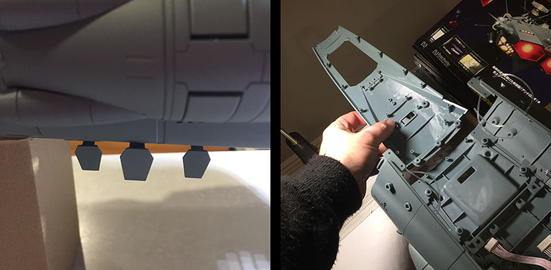
Left: the port side has those same two hatches to install, so I take care of that. But you’re seeing three hatches here. The middle one was installed earlier, before the hull segments were attached. Now that they’re in place, this hatch droops down and hangs there. It won’t stay in the closed position. So that’s pretty stupid.
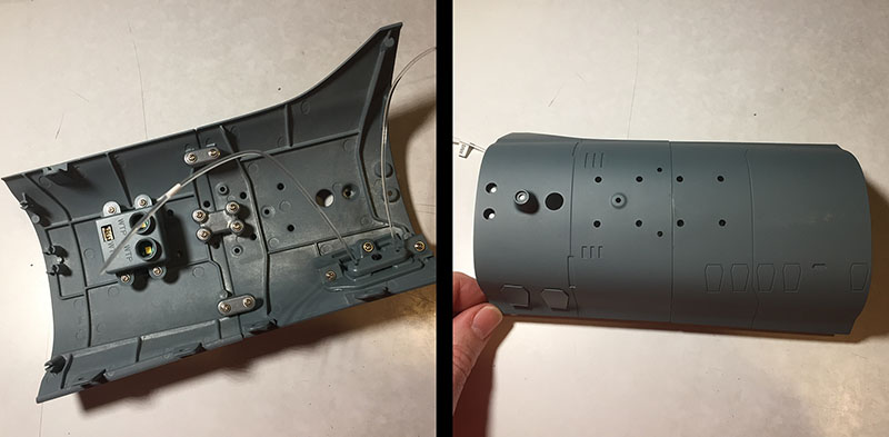
Right: there’s one more piece of the belly that came in this volume, but we don’t attach it yet. This is the first piece I’ve seen that will go all the way to the engine nozzle.
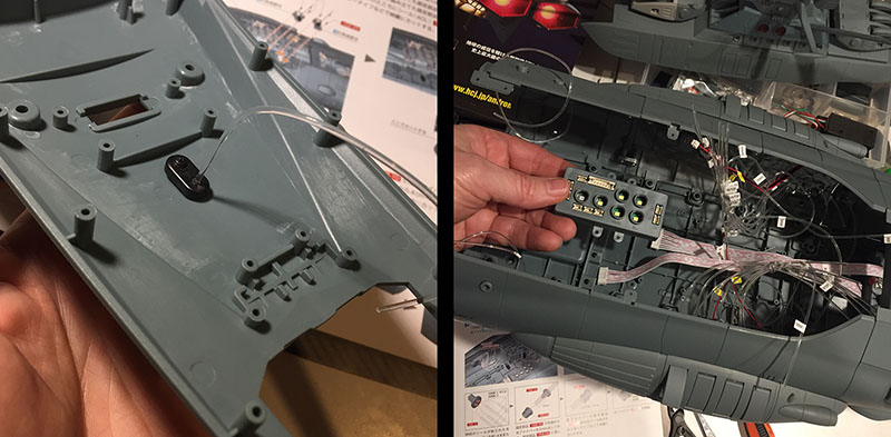
Left: that segment gets one light attached to it, then we’ll put it aside for future use.
Right: next, we’re going to install a new distributor box in the cavity we just created.
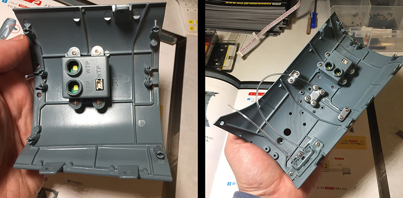
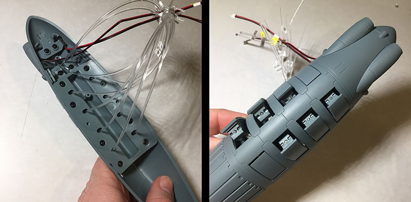
Left: Installation complete. The yellow tabs are LEDs that will feed lights into the many fiber optics (four per slot). The sockets are for wires leading to bulbs. And now that this is in place, you know what time it is!
Right: Time to tame this noodle storm!

Left: All noodles have been gathered and capped.
Right: All noodles have been plugged into their respective ports. MAN, that’s satisfying. And the good news is that the tension has evened out on those modules in the side bulges. They’re staying closed like they’re supposed to. That’s a big relief.
Now, remember how each of the side panels had a mini-distributor box on it? That’s where all the fibers from the bulge parts plug in. Then a wire relays power to the mini-boxes from the larger one we just put in. You can see those relay wires in the lower part of the photo at right. That takes care of EVERYTHING in this area.
Left: on the other hand, there’s still an unoccupied port in the middle of the distributor box. It’s waiting for something else to be plugged in. I’m guessing it’s the first main gun turret, which still hasn’t been installed. It’s been sitting off to the side ever since it was assembled way back in Volume 11.
Right: the final step in Volume 48 is to attach two metal braces to the section we’ve just assembled. The first one screws on tight. The second one (left side of photo) just sits there. The two screws just drop into the holes and don’t grip anything. I hope this gets addressed in the future.
Whew. Now THAT was a big move. Time to reclaim some desk space.
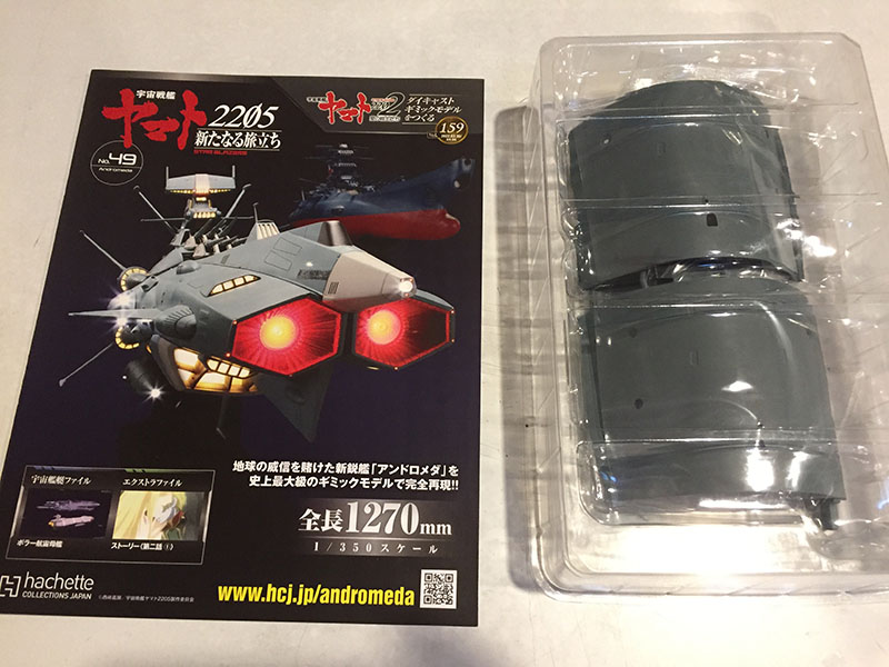
We’re all the way up to Volume 49.
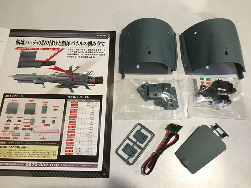
This is the first two give us two metal hull segments at once.
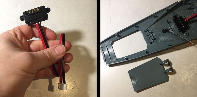
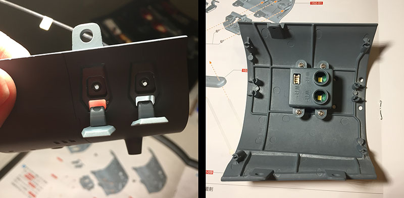
Arguably the most important component of the entire build: the power connector. This will attach to a reciprocal unit built into the support base. It gets attached to that unused belly panel we haven’t connected to the rest of the body yet. Then we’ll install the hatch for the hangar bay.
It goes on easy enough, but…it won’t stay closed all the way. Not cool, Hachette. Points off for that.
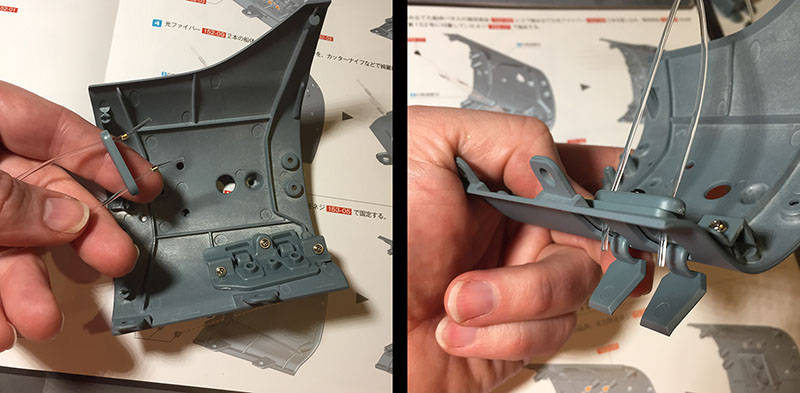
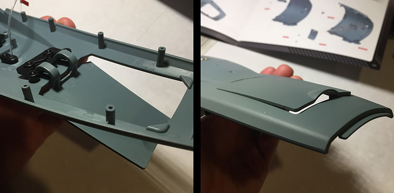
The rest of this volume is simple; just attach some fibers to the hull segments. Each has two, located close together and secured by the same hold-down clamp.
Each one has a little popup light that will be positioned on the backside of the UNCF emblem. But we’re not attaching them to the hull yet. They’ll be part of the stern assembly.
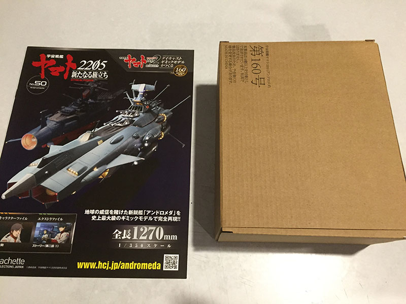
Volume 50! What’s in the box?
Looks like we’re taking a short break from the ship to work on the display stand. The one for Yamato was much harder to assemble than I expected, due entirely to that short screwdriver. It was very hard on the hand. Now that I’ve got the longer screwdriver, I’m actually relishing it.
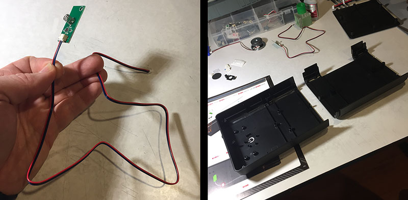
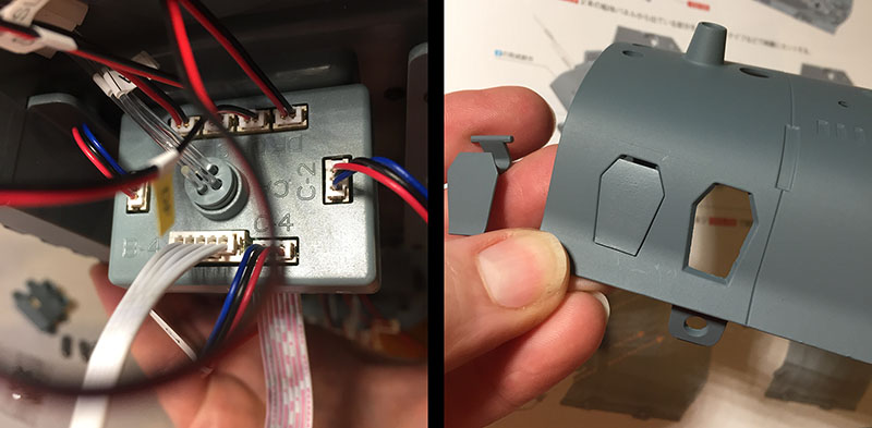
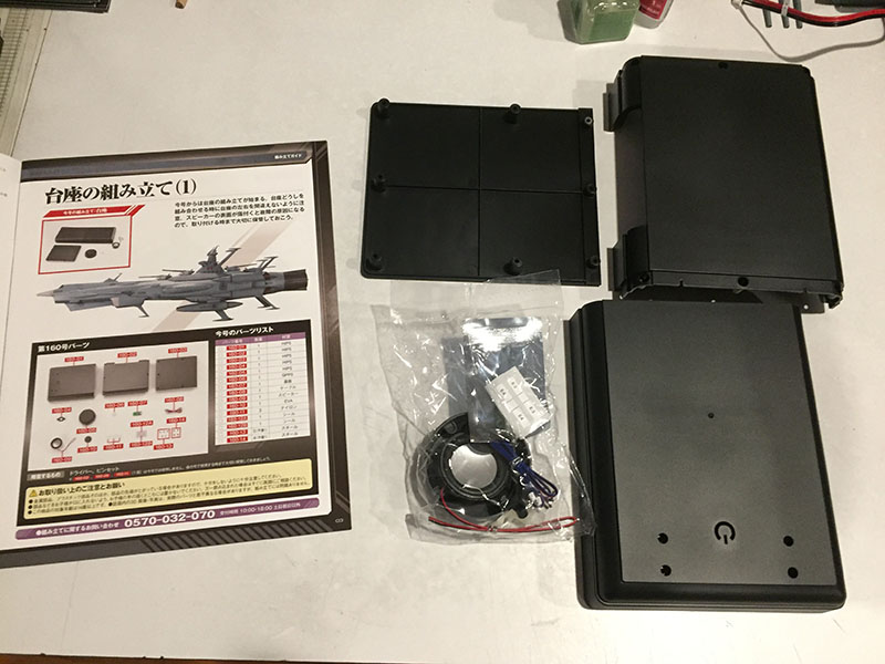
First, there’s this little circuit board with a pressure spring on it. This will go directly under the power button, which you can see cut out of the platform.
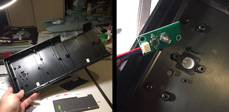
After we attach the two platform pieces together, a buffer goes under the power button and the spring gets attached to the buffer.
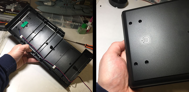
With that done, we flip it over and you can that the “power button” isn’t a button at all. It’s a cutout with a window under it. The spring is sensitive to the slightest touch.
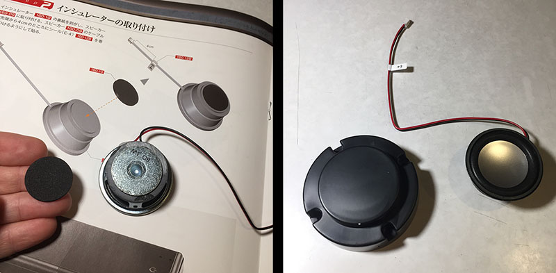
The last step in this volume is even simpler. Attach an insulator pad to the speaker. And just like that, we’re 50 volumes down with ten to go.
one of the common themes seems to be little problems that end up being like death by paper cuts…
like it was rushed into production without being fully thought through…